The ic was not even slightly warm so I doubt it burned out. It must have just reset itself. In any event, what do you suggest that I use so that I can easily monitor the output?
Use a different LED, a standard 3 mm led with a forward current of 20ma and use a 330 ohm resistor for it....
Or use a transistor to switch the current LED you have connected, since the IC can not supply enough current to turn the LED on.... since that looks like a 12 Volt CREE/LUXEON LED...
I replaced the LED with a smaller one and added the resistor in series with it. I also replaced the IC in case the output was burned out. Still nothing. Any ideas? I'm getting pretty frustrated with it at this point.
I replaced the LED with a smaller one and added the resistor in series with it. I also replaced the IC in case the output was burned out. Still nothing. Any ideas? I'm getting pretty frustrated with it at this point.
What seems to be the issue that you are having? The LED is not coming on?? Are you sure the circuit is properly operating for the LED to light up? Do you have the LED connected properly? Try flipping the LED's leads around and see if that helps...
I am as sure as I can be that it is all hooked up right. The polarity on the LED is correct. I am going to tear it all apart and start fresh tomorrow.
I am assuming that using the LED to test the output is reasonable? It should light when the signal is applied for more than 1.5 seconds if everything is hooked up right? If not then I am beyond confused. Seriously thinking of going with a microcontroller at this point. Seems like overkill but wouldn't it be much easier?
You can refer to the image of how to hook up the circuit. I have numbered the pinout of each inverter inside the CD40106B. I also included two LEDs, each with a 220ohm series resistor. This is not shown in the circuit diagram.
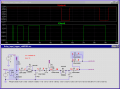
It also give me a chance to play around with the following interesting piece of software. Try it.
Last question (for now) when counting the pins on my IC I am confused. There is a notch on one end of the chip and a dot on the other. So which end is considered "1"?
I have put everything together as pictured in the diagram. I want to make sure I am clear on the function.
When power is applied the red LED lights and after a second it goes off and the yellow LED lights. After another second the yellow LED goes off and the red LED lights again. It then stays in this state until power is removed. Applying power to the "input" (the wire attached to pin 3) doesn't seem to change the state of the circuit no matter what length of time it is applied.
So am I missing something? Is power only applied to the circuit during the differentiation of pulses or is it on all the time and somehow I am not activating the input (pin 3) properly?
I think with the circuit as is I can use it but was just curious about how the input worked. I think if I just apply power when the pulses are being differentiated (which means the pulses themselves are actually the power being applied) then it will work. When a short pulse in applied, only the red LED lights. When a longer pulse is applied, then the yellow LED lights and that will be what triggers my latch. I understand how to adjust the timing of each LED lighting and have played with it a bit.
Now I need to get it set up to activate my latch. I am thinking of driving it with transistors to step up the current from the tiny IC current to the current required by the latch. Other than that I just need to do some final testing hooking the two circuits together and make sure they actually work together like they should.
This is starting to really come together! I have never been happier to see blinking LED's!
Applying power to the "input" (the wire attached to pin 3) doesn't seem to change the state of the circuit no matter what length of time it is applied.
The setup assumes that you have "something" already connected to pin#3 of IC 40106B.
If you just want to test out the circuit without the timing signal, you will need to place an extra resistor(any value higher than 1KΩ will work) from pin#3 to 0V so that pin#3 voltage is not floating.
Do that and your circuit will operate correctly when you then apply your signals to Pin#3; after power ON and the circuit stabilized.
OMG, it works! Unreal. The silicone is finally doing my bidding! Today's project is to actually hook it to the circuit I plan on using it with to be sure that its input will work with the circuit I've built. I have no reason to believe it won't.
I will update you shortly. I know you're probably hanging on every update.
So I went back to my original board to measure the points that were to be my signal in. Apparently I was smoking crack because I cannot find the point which was giving me my original signal. I have no idea how I could have confused this. Whatever.
Anyway, I poked around on the board some more and have found a point which gives approx 2 volts (where the other source I thought I had found gave 3 volts) which is apparently not enough to act as a "high" signal for the circuit we have been discussing to work with. So I guess I need to figure out how to turn 2 volts into something large enough to trip the circuit I've built.
On the up side I haven't managed to screw up the circuit you folks have coached me on and I've been messing with it all afternoon!
Edit: Or my other option is I have found a few places on the board that produce voltage in relation to each other but not the main negative coming from the battery pack. In other words, placing one lead on the negative end of the battery and the other on a certain location yields no voltage. But placing the negative lead of the meter on a different spot and the positive on the certain location does yield the voltage change I need. Since the ground does not seem to be shared I am having trouble figuring out how I would use it to trigger my circuit. Can I use the 2 independent spots vs a single spot and a common ground? I hope my description is clear enough.
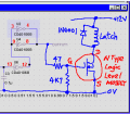
To overcome this voltage problem you would need to add a transistor. The changes are marked by blocks of light blue color.
The addition of the transistor enable the circuit to take signal of 1V or higher, which is what you've got at this moment from the output of the finger print unit. You can use any small NPN transistor you have at hand. Ask here if you are not sure if the part number fits.
However, the transistor inverts the logic signal sense so we have to remove one input inverter stage to "counter" the logic level change. This unused gate is reused at the output to boost the signal level.
Happy to report that I worked on this using a few transistors I had on hand. The first didn't work for some reason. I did some trouble shooting and switched some things around. Now it is working!
Now to poke around and do a bit more testing just to be absolutely certain I don't get any false positives.
What hopefully is the final stage is getting it to work my latch. The latch requires 12 volts to fire and open the door. So now I have to figure out the best way to turn a blinking LED into a 12 volt signal. Are transistors the best way to do this or would a relay be better?
So now I have to figure out the best way to turn a blinking LED into a 12 volt signal. Are transistors the best way to do this or would a relay be better?
What function is this LED suppose to indicate? The LED I am referring to is the one that indicates a proper finger print swipe (the yellow one in the circuit you made for me). In other words, it only goes on when the door is supposed to open.
What condition leads to the blinking of the LED? Someone places his finger on the sensor...etc? It doesn't really blink I guess. It is the yellow LED in the circuit you made for me. It just lights when the proper print is swiped.
Does it gets its supply from the 6V circuit? I am afraid supplying it from the 6v battery pack that everything else is running off of will drain the pack too fast. I am prepared to provide a separate pack just to run the latch. I don't remember if I mentioned to run the latch properly it requires 12v anyway so (although I am sure the is a way) I don't know how to do that off of a 6 volt pack. I am trying to keep it as simple as possible here.
How fast does it blinks? Answers like a few times per seconds or once per second would do. Again, it is the yellow LED in the circuit that you made for me. It goes on approx 2 seconds after the proper fingerprint is swiped and stays on for about a second. I can adjust the "on" time with resistors as you pointed out.
How long will the blinking process last, in seconds? The yellow LED currently stays on about one second but can be adjusted by adding or taking away resistors as you pointed out.
Do you want the latch to stay energized for the whole period until the LED stop blinking? Or only for a fixed period? How long? It only needs to stay energized for a very short time. Maybe half a second at the most. The door is spring loaded so as soon as the latch is out of the way it pops open on its own.
It is not the blinking LED but the output LED. The LED that turns ON for a second or more when the correct finger is swiped.
So basically you just want to know how to use the output signal to drive a 12V latch.
For that I'll need to know the ohmic resistance of the 12V latch coil to determine the current (or the current required if you know it already). Please measure it using a DVM in the ohm range or measure the current via current range.
A transistor, either a simple one or a darlington one is what it'll take to do the job, depends on current of the latch.
The resistance is 8.5 ohms according to my multimeter.
(my meter has several range settings for resistance. when I put it on the 200 setting it reads 8.5. when I put it on the 2000 setting it reads 8. I hope I am reading it right when I say the resistance is 8.5 ohms. I hate this meter, I want to get an auto ranging one. 99 times out of 100 I only use the ohm meter as a continuity checker.)
For this you can use a Darlington NPN transistor to do the job. The base pin of the transistor is connected to the circuit output via a 1KΩ resistor. This output will go high when a valid finger is swiped.
The datasheet of the TIP12x NPN darlington is also attached below. The Darlington is actually two transistors inside one casing so can offer very high gain. You can use other NPN power Darlington transistors if you have difficult getting hold of this particular one.
Another option is to use a logic level MOSFET in place of the Darlington. The component count is about the same but the resistor value will be different and connection will be to 0V instead. See below.
As for all loading inductive, a back emf diode is required across the latch and in view of the infrequent operation of the latch, a 1N400x diode will suffice as the load current in the latch will die down rather quickly. Normally, others will advise you to use 1N5401 which is a much beefier one.
Note that 12V is only used to power the latch. Other part of your circuit can be powered by the 6V dry battery instead.
I (well you) did it! I got the door to open with the swipe of my finger! Now I have to get everything off this crowded breadboard and permanently soldered in place. Any suggestions on layout of the circuit to maximize space efficiency?
I was thinking of adding a light to the inside of the box that I am securing. Of course it would only be open when the door is open. The spring that "spring loads" the door to pop it when the latch is activated has a built in switch. The problem is that the switch is in the "open" position when the door is open. It would be easier of course if the switch closed when the door was open then I could just simply wire it up. Anyway, is there a very simple way to switch the open/closed position of the switch? I have inspected the switch closely and there is no way to physically do it at the switch itself.
 Facebook
 Google
 GitHub
 Linkedin


")