Circuit: half works/half doesn't

Thread Starter

Tony Elliott

Joined May 8, 2015
160
Hi All,
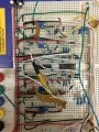
I have made this circuit, it is a voltage controlled amplifier.
The signal in works but the voltage control (CV) doesn't. What is the best way of finding my error?
I have checked the resistor values. All the connections and changed all the active components so far.
 

Attachments

Thread Starter

Tony Elliott

Joined May 8, 2015
160
What do you mean, "I can just hear it". are you connected directly to a headphone / speaker or are you sending the signal through an amplifier?

Also, turn your Bias Adjust up so it is at 1.2 to 1.4V (or more).
There is an oscillator connected to the CV when I turn it up in frequency I can just hear it. The circuit is connected to a hifi.
 

Thread Starter

Tony Elliott

Joined May 8, 2015
160
One thing I should of said was that the q4 transistor was around the wrong way when I first turned it on resulting in the 2n3906 transistor burning out. I then corrected this and replaced all the active components on the circuit. Could this have effected any of my passive components?
 

GopherT

Joined Nov 23, 2012
8,009
Measure the voltage at Vout when it is connected to your HiFi. The input impedance of your HiFi may be too low and attenuating the signal of the VCA. If so, you'll need a buffer (pre-amp) between your VCA and HiFi.

Also, BiasA POT should be adjusted to have 0V at Vout with no signal.

Are there people on the webs who have had success with this circuit, or has it garnered little enthusiasm because it doesn't work?
 
Top