Facebook
 Google
 GitHub
 Linkedin
Hello, everyone!
I'm quite new to electronics and I was hoping for some feedback.
I'm building a device that will trigger an electromagnet for a specific period of time repeatedly.
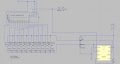
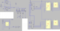
The core is a simple circuit that powers the electromagnet (1). This circuit runs through a relay that is triggered by a 555 timer (2). R2 of this timer is attached to a 12-pole rotary switch which allows different delay times to be selected. 11 options are just different resistors that keep the cycle length fixed (3) but the last option feeds through a set of MOSFETs paired with resistors. These MOSFETs are triggered, one-by-one, by a decade counter (4) so that the delay time changes with each pulse instead of remaining fixed.
The power for the timer comes from a flip flop triggered by a countdown system made of two CD40192 up/down counters (5). The output from the 40192s also feeds into 7-segment LED drivers (HEF4543) which power the 7-segment displays (6).
The clock pulse for the countdown timer is provided by a second 555 chip calibrated for a 1s cycle (7).
Section 8 is the input switches, all debounced and put through a Schmitt inverter.
Functionally, the device works like this: after turning it on, use the Up/Down buttons to set the countdown timer to the desired delay. Then turn the knob to specify the interval for the magnet. Finally, press Start. The display counts down the specified number of seconds, and once it hits zero, it activates the pulse timer that controls the magnet. Then the magnet is triggered repeatedly until the device is turned off.
Have I made any glaring mistakes? Does everything seem to be wired correctly? From reading other threads I gather that the Vin is supposed to be at the top left. When making the schematic I organized it in a functional (to me) order.
I realize this is a tall order and if this is the wrong place to seek this kind of help I apologize. I appreciate any assistance you can give me.
Thank you!
Datasheets:
http://www.alldatasheet.net/datasheet-pdf/pdf/158029/TI/CD40192B.html
http://www.nxp.com/documents/data_sheet/HEF4543B.pdf
http://processmodeling.org/theory/electronics/ref/40xxx/40106.PDF
I'm quite new to electronics and I was hoping for some feedback.
I'm building a device that will trigger an electromagnet for a specific period of time repeatedly.
The core is a simple circuit that powers the electromagnet (1). This circuit runs through a relay that is triggered by a 555 timer (2). R2 of this timer is attached to a 12-pole rotary switch which allows different delay times to be selected. 11 options are just different resistors that keep the cycle length fixed (3) but the last option feeds through a set of MOSFETs paired with resistors. These MOSFETs are triggered, one-by-one, by a decade counter (4) so that the delay time changes with each pulse instead of remaining fixed.
The power for the timer comes from a flip flop triggered by a countdown system made of two CD40192 up/down counters (5). The output from the 40192s also feeds into 7-segment LED drivers (HEF4543) which power the 7-segment displays (6).
The clock pulse for the countdown timer is provided by a second 555 chip calibrated for a 1s cycle (7).
Section 8 is the input switches, all debounced and put through a Schmitt inverter.
Functionally, the device works like this: after turning it on, use the Up/Down buttons to set the countdown timer to the desired delay. Then turn the knob to specify the interval for the magnet. Finally, press Start. The display counts down the specified number of seconds, and once it hits zero, it activates the pulse timer that controls the magnet. Then the magnet is triggered repeatedly until the device is turned off.
Have I made any glaring mistakes? Does everything seem to be wired correctly? From reading other threads I gather that the Vin is supposed to be at the top left. When making the schematic I organized it in a functional (to me) order.
I realize this is a tall order and if this is the wrong place to seek this kind of help I apologize. I appreciate any assistance you can give me.
Thank you!
Datasheets:
http://www.alldatasheet.net/datasheet-pdf/pdf/158029/TI/CD40192B.html
http://www.nxp.com/documents/data_sheet/HEF4543B.pdf
http://processmodeling.org/theory/electronics/ref/40xxx/40106.PDF
Attachments
-
656.6 KB Views: 64
")