Circuit breaker help!

Thread Starter

WCR

Joined May 1, 2024
10
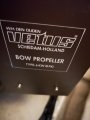
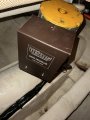
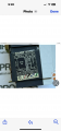
I was hoping to receive some advice on matching an existing circuit breaker that is failed. I’m not electrician or super knowledgeable in the field. This particular breaker is being used in a way I have not seen before. It used on an Italian boat to interrupt the 24 V DC bow thruster. The manufacturer from 1994 attached a bar on each side to connect all 3 poles to 1 DC cable. I do not have information about the Bow thruster with me. I am simply trying to match the existing breaker and in a similar configuration to the one that I have so that I do not need to make changes to the panel. Please see the attached photos. The first photo where the breaker is installed in a black panel is the existing breaker that has failed. The second two photos are of a breaker that is available on eBay. My problem is I’m not familiar with the abbreviations on each breaker and would like advice if anyone believes this breaker to be purchased would be a match. Thank you for your help!
 

Attachments

LowQCab

Joined Nov 6, 2012
5,101
Paralleling a 3-Pole-Circuit-Breaker, especially in a DC-Circuit, IN SALT-AIR, is very poor engineering.

I would replace it with a single 300-Amp Fuse, at the Battery, not mounted near the Motor(s).

These ANL style Fuses are available up to 600-Amps.

ANL Fuse Specifications .PNG
.
.
.
 

Thread Starter

WCR

Joined May 1, 2024
10
Thank you for your reply.
All of the boat is original from Italy. It’s a 60 foot Ferretti. They also used all AC breakers on the full DC panels.

I couldn’t understand why this type of breaker was used. As I’m not super familiar with the conversion they were trying to accomplish. Since they set up all polls in parallel do you believe they were trying to achieve a 300 amp breaker?
Could you recommend any type of fuse/ breaker that you can turn on and off?
Also, just curious from the photos I uploaded of the breaker that I could purchase is it actually a 40 amp breaker or 100 amp?
Thanks again for your help.
 

boostbuck

Joined Oct 5, 2017
1,037
Paralleling circuit breakers to increase current capacity is not uncommon - see this for example: Paralleling ... Low Voltage Power Breakers

I've used this configuration for extra-low voltage DC circuitry - GE for example give ratings for their low-voltage domestic breakers for DC operation. Standard breakers are considerably cheaper than specialised DC or extra-high capacity units.
 

boostbuck

Joined Oct 5, 2017
1,037
The MA100 is a 100amp breaker, so it is set up as a single 300amp breaker (although DC rating breaking will be different from AC I believe). I note from your photo it appears to be rated to 250V DC.

The disadvantage of a fuse is not resettable and cannot conveniently be used as a disconnect.
 

norfolknick

Joined Aug 15, 2020
9
The MA100 is a 100amp breaker, so it is set up as a single 300amp breaker (although DC rating breaking will be different from AC I believe). I note from your photo it appears to be rated to 250V DC.

The disadvantage of a fuse is not resettable and cannot conveniently be used as a disconnect.
The label on the original breaker shows max DC voltage is 250 at 15A. So paralleling 3 gives 45A. The label on the ebay is the same, so buy it and wire it the same as the original .... job done.:)
 

norfolknick

Joined Aug 15, 2020
9
That figure is Icu rated in units of kA, so Icu is 15 THOUSAND amps. That doesn't affect the rated trip value of 100A, so paralleled it is a 300amp breaker.
It's a small "k" which is the "k factor". For European devices it's usually = 100% of A. I would need to read up a bit but, it's something to do with the ability of the breaker to trip at current "A" without internal damage to the breaker itself. So it is 15A per pole.
 

boostbuck

Joined Oct 5, 2017
1,037
haha well I must say Icu = 15,000 amps seemed excessively robust! I'm no expert on the finer details, but this k factor is a bit ambiguous. Shame they used 'k' since SI had pretty much claimed that for kilo - very confusing.

Is there a clear explanation for k factor anywhere?
 

boostbuck

Joined Oct 5, 2017
1,037
best I can do:

" The K-factor is the ratio of the rated maximum voltage to the lowest operating voltage for which the inverse relationship between the operating voltage and the interrupting current holds true. The K-factor is a limit for derating the interrupting current for a varying operating voltage."

hmmm.... not so clear TBH. kA for 250V DC is 15? Derating is less likely to trip, or more? 15 means what? A fifteenth, or 15 times? Of what?
 

Thread Starter

WCR

Joined May 1, 2024
10
You guys are all so intelligent! So much of this is over my head. I found a photo of the bthruster, which says 6KW (8PK)
So I’m guessing that needs at least 250 amp breaker is that correct and that is why then they attached three in parallel? To achieve 300 amp?

And the original photos I sent my existing breaker in the black panel said In100A . I am assuming that means 100 amp? The one on eBay underneath the MA100 it shows In40A so I’m guessing that’s a 40 amp? I was getting confused because they both say MA100

am I understanding this correctly?
So this would mean it’s the wrong breaker?

Thanks again for your help and trying to keep this simple enough so that I can understand it.
 

Attachments

norfolknick

Joined Aug 15, 2020
9
You guys are all so intelligent! So much of this is over my head. I found a photo of the bthruster, which says 6KW (8PK)
So I’m guessing that needs at least 250 amp breaker is that correct and that is why then they attached three in parallel? To achieve 300 amp?

And the original photos I sent my existing breaker in the black panel said In100A . I am assuming that means 100 amp? The one on eBay underneath the MA100 it shows In40A so I’m guessing that’s a 40 amp? I was getting confused because they both say MA100

am I understanding this correctly?
So this would mean it’s the wrong breaker?

Thanks again for your help and trying to keep this simple enough so that I can understand it.
Having seen the pics of the thruster, it looks like I got it all wrong and I apologise. 6KW at 24v is indeed 250A, so a breaker of 3 x 100 would be correct. I am confused by the DC part of the label on the breaker and I will have to do some research!
 

boostbuck

Joined Oct 5, 2017
1,037
It's a small "k" which is the "k factor".
Well, after a bit of reading up, it seems that my original supposition of kilo-amps is correct, and Icu in that range is not unreasonable. The k-factor current derating (a fractional value up to max=1, or 100%) appears to be an issue of adjusting the allowed current switching to change as supply voltage diminishes, something apparently best ignored per the general assumption that it should be taken as 100%.
 

MisterBill2

Joined Jan 23, 2018
27,271
Finding a replacement breaker that has the same connections inside the panel could be a challenge. And that ^KW rating certainly does mean 250 amps from a 24 volt supply. Now a question: Is that breaker used for the on/off control of the motor?? or is there a separate control someplace else in the power line? Generally a breaker is a poor choice for a control switch because they do wear out much faster. IF you are able to get a three-phase breaker rated 100 amps, that will be the way to go.
And now some advice, which is to use individual wires good for 100 amps to each breaker and carefully join them with a low-resistance joint some distance from that breaker. Then use a DC clamp on to verify equal current in all three. Drawing 250 amps thru only two breakers will quickly wear them out from tripping.
If you can get a single 300 amp breaker, that is much better.
If there is an external control, then you can use a single fuse.
 

Thread Starter

WCR

Joined May 1, 2024
10
Thanks again for your support.
Yes, the breaker is also the on and off for the motor. Because I’ve had such a challenge locating the same breaker same amperage and footprint. I was considering changing it out. to a simple DC, single pole, 300 amp, switchable, thermal breaker. With the low cost, It would leave me plenty of funds to produce a small cover in the panel to house the new breaker.
Thoughts?
Ty
 

boostbuck

Joined Oct 5, 2017
1,037
Sounds ok to me. Make sure you confirm the manufacturer's DC specifications meet your requirements.
But I would expect a 3-phase breaker at 100amps will be plenty cheaper than a 300 amp single IF it will fit the constraints of the enclosure.
 

MisterBill2

Joined Jan 23, 2018
27,271
IF it serves as the switch, I suggest using a separate fuse and a single switch. The reason for the present triple breaker failing is probably because they do not all open or close at exactly the same time, and so one breaker is opening and closing the full 250 amps. It is not likely that a 300 amp fuse will fail without a serious overload if you get one rated for motor starting service, and a switch made for that current will last much longer. Of course, a DC contactor rated for that current, plus a fuse, would probably be a lot cheaper, and the switch on the control panel will be much smaller and easier to operate..
 

MisterBill2

Joined Jan 23, 2018
27,271
I am guessing that during maneuvers where a bow thruster is required, that it may switch on and off a few times. That is far from the intended purpose of circuit breakers. An adequate DC contactor, like those used for different applications on electric fork lifts, and even starter motors, is intended for more frequent operation at high load currents.
As for intelligence, certainly there is a fair bit of brainpower here, but also, what is even more important, is the access to hundreds of years of first-hand experience. For many of the questions the response could be "Been there and done that, AND here is what worked and what did not work."
Experience can be a great teacher, although sometimes a very brutal one. So it can be vastly less painful to learn from the experience of others.
And, of course, sometimes it is much more fun to learn on your own.
 

LowQCab

Joined Nov 6, 2012
5,101
Does this Bow-Thruster NOT have a Speed and Direction-Control-Box ??????
Why is no one addressing this very important point ?


If it does have a Control-Box,
there should be no reason to "Switch" the Power On & Off with the Breaker, or any other type of Switch.

As in the first response by me,
I vote for using a single Large-ANL style-Fuse.
( Fuse-Holders are readily available, or, it's simple to build your own design.

Using a 3-Pole-Breaker as a Single-Pole-Switch is just asking for a failure,
especially in a Salt-Air-Environment.

It's not IF a 3-Pole-Breaker will fail, it's only a matter of WHEN it will fail.


If the Control-Box pulls excessive Quiescent-Current when supposedly turned "Off",
then a simple Marine-Grade-Battery-Switch
can be installed for Battery-disconnection during Boat-storage-conditions.
( You do keep the Batteries on a proper Battery-Maintainer at all times, right ? )

Sometimes Equipment-Manufacturers, or, ( possibly in this case ), Boat-Builders, make dumb decisions.
.
.
.
 
Top