 Facebook
 Google
 GitHub
 Linkedin
I am having trouble with 2 fairly straightforward problems.
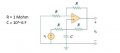
In the first, I am attempting to analyze the following:

Capacitors are treated as open circuits in DC. With this assumption, nodal analysis yields the following: Vo = 2 * V1, and Vo = 2 * V1 - Vi. These 2 equations seem to be contradictory, and i'm not sure how to resolve the contradiction.
In the last problem, shown below, I think I have the solution, but my simulation of it in multisim gives unexpected results:

Through nodal analysis I get io = 20,000is, but in multisim the behavior of the output is unpredictable. Is that not the right interpretation of the above circuit? Here is my multisim version of it, in case any of you might be able to see where I erred:

In the first, I am attempting to analyze the following:
Capacitors are treated as open circuits in DC. With this assumption, nodal analysis yields the following: Vo = 2 * V1, and Vo = 2 * V1 - Vi. These 2 equations seem to be contradictory, and i'm not sure how to resolve the contradiction.
In the last problem, shown below, I think I have the solution, but my simulation of it in multisim gives unexpected results:
Through nodal analysis I get io = 20,000is, but in multisim the behavior of the output is unpredictable. Is that not the right interpretation of the above circuit? Here is my multisim version of it, in case any of you might be able to see where I erred:
Attachments
-
 29.3 KB Views: 1
 -
 142.6 KB Views: 2
 -
 149.5 KB Views: 3


