Facebook
 Google
 GitHub
 Linkedin
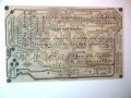
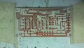
Yes. I tried using catalog paper, which seemed to be a favorite, soaked and soaked, rubbed and rubbed, scrubbed with toothbrush; only to discover that I had incomplete toner transfer.Back when I was making PCBs I used to immerse in water until the paper very soft and easy to tear, so as I remove it part of the paper remains on top of the transferred toner. Have you ever tried that?
Choosing the right laser printer for making PCBs.
- Thread starter Ivan Ivanov
- Start date
")