
 Facebook
 Google
 GitHub
 Linkedin
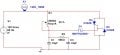
hey guys. SO i've been given the assignment of designing and building a dimmer for a 40watt 120v bulb using 2 SCRs. A triac would be nice, but no, must be SCRs.
So i made the triac equivilant lol.
Now in multisim, stuff works using the "virtual" parts. However, i can only get an output voltage on the meter of 0-65V
So when i try to substitute in real parts in Multisim, i get about 20 minutes of convergence errors, followed by a circuit that sits at 66V across the light bulb and responds to no control. My guess is, i've picked the wrong parts, OR, i've wired something wrong. Can someone point me in the right direction?
Ive found by varying the 2 capacitor values i can set my "start" voltage essentially. The bulb says 100W, but, i can't change it. Should be 40W. My sine wave phase shifts nicely.
Thanks in advance guys.
So i made the triac equivilant lol.
Now in multisim, stuff works using the "virtual" parts. However, i can only get an output voltage on the meter of 0-65V
So when i try to substitute in real parts in Multisim, i get about 20 minutes of convergence errors, followed by a circuit that sits at 66V across the light bulb and responds to no control. My guess is, i've picked the wrong parts, OR, i've wired something wrong. Can someone point me in the right direction?
Ive found by varying the 2 capacitor values i can set my "start" voltage essentially. The bulb says 100W, but, i can't change it. Should be 40W. My sine wave phase shifts nicely.
Thanks in advance guys.
Attachments
-
 31.4 KB Views: 109






