Choosing high voltage synchronous buck converter IC

Thread Starter

SiCEngineer

Joined May 22, 2019
442
Hello,

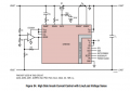
I have designed a power supply which I am simulating in LTSpice. I am trying now to choose a control IC for the synchronous buck converter which varies the voltage applied to a fixed frequency resonant half bridge converter.

However, my input voltage is 270VDC nominal, and I cannot find for the life of me an IC in LTSpice that will be capable of doing this, since the switch voltage will be too high for the maximum rating for the IC.

What other alternatives do I have if I want to control a high voltage buck converter?
 

Marley

Joined Apr 4, 2016
502
You would normally use a transformer instead of a simple inductor. This datasheet here shows a possible solution.
The output does not have to be isolated from the supply, in which case you would not need the opto-isolator in the feedback circuit. Also in your case, because your supply is already DC, you also do not need the bridge rectifier.

Dangerous voltage - take great care!
 

Thread Starter

SiCEngineer

Joined May 22, 2019
442
Hi! Thanks for your reply. Alongside using a sense resistor to translate the inductor current to a voltage, I also believe I will need information regarding the voltage on the secondary side of my transformer (since this is what I ultimately need to control the level of). After looking in the data sheet, I have identified one circuit which I may be able to use with the 9100. I have attached it.

It says it has current sensing and both input/output voltage sense. Would this be something I could implement, do you believe? I am quite confused how the output voltage is being sensed - it looks to me like it is using an opamp to compare the input to the output voltage and feeding that to the ADIN2 pin. But I am unsure?
 

Attachments

Thread Starter

SiCEngineer

Joined May 22, 2019
442
You would normally use a transformer instead of a simple inductor. This datasheet here shows a possible solution.
The output does not have to be isolated from the supply, in which case you would not need the opto-isolator in the feedback circuit. Also in your case, because your supply is already DC, you also do not need the bridge rectifier.

Dangerous voltage - take great care!
My resonant half bridge is isolated, the buck converter just regulates the voltage applied to it. I should have mentioned that my output power on the secondary side of the transformer is>600W, and my switching frequency 300kHz. Probably, rules out the suggestion of yours (my bad).
 

Danko

Joined Nov 22, 2017
1,835
It says it has current sensing and both input/output voltage sense. Would this be something I could implement, do you believe? I am quite confused how the output voltage is being sensed - it looks to me like it is using an opamp to compare the input to the output voltage and feeding that to the ADIN2 pin. But I am unsure?
It is differential measurement of VBUS voltage.
+IN of op amp senses voltage between common wire and VBUS+.
-IN of op amp senses voltage between common wire and VBUS-.
On OUT of op amp we have difference of +IN and -IN voltages, V_diff,
which is proportional to VBUS voltage.
EDIT:
LTM9100 is controller for ON/OFF switch Q1, connected between your 270V power supply and LOAD,
so VBUS is 270V line.
 
Last edited:

ronsimpson

Joined Oct 7, 2019
3,037
vin 270 volts. (you almost have to use parts built for power line power supplies)
Vout (isolated) What voltage?
600 watts.
300khz (Why?)
resonant
half bridge
synchronous (I don not use synchronous unless the output voltage is low and the current is high.)
Buck ?

Something like this?
1572565410422.png
 

Thread Starter

SiCEngineer

Joined May 22, 2019
442
vin 270 volts. (you almost have to use parts built for power line power supplies)
Vout (isolated) What voltage?
600 watts.
300khz (Why?)
resonant
half bridge
synchronous (I don not use synchronous unless the output voltage is low and the current is high.)
Buck ?

Something like this?
View attachment 190339
Isolated Vout, 6kV. 300kHz, which is flexible (can be more, or less if I design it - but should be fixed). This is to shrink the passive components, and to lead to smallest overall volume solution. I use synchronous buck but works non-syncrhonous also.

What about this IC, anything wrong with it? https://www.analog.com/media/en/technical-documentation/data-sheets/lt1241.pdf
 
Top