Facebook
 Google
 GitHub
 Linkedin
Greetings,
I am currently building an IR remote control system to control the speed of a motor. I was told that I should install a few bypass capacitors to cut down on noise. However, I am unsure of how to determine the placement and value of the capacitor. I don't want to mess up the timing of my 555 timers.
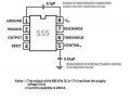
Here's the circuit schematic I'm using:

Here's the specs for the motor I'm using:
Torque: 0.1 Nm
Total Power: 11 Watts
Maximum Current: 2.44 A
I appreciate any feedback! Thanks
I am currently building an IR remote control system to control the speed of a motor. I was told that I should install a few bypass capacitors to cut down on noise. However, I am unsure of how to determine the placement and value of the capacitor. I don't want to mess up the timing of my 555 timers.
Here's the circuit schematic I'm using:
Here's the specs for the motor I'm using:
Torque: 0.1 Nm
Total Power: 11 Watts
Maximum Current: 2.44 A
I appreciate any feedback! Thanks