Chinese power supply troubleshooting (2)

Thread Starter

Kierant

Joined Mar 4, 2020
3
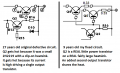
Hi Guys, greetings from NZ. I've built one of these 0 - 30v Chinese Power supplies, & I'm starting to tear my hair out with it. I'm using it to supply 4v to a motor out of an old drill. ( It seemed the cheapest option at the time! ) The power supply works great on the Test Bench, using low value ( 2.7Ω ) 10W resistor as a load. The motor runs fine when supplied with 4v from my Test Bench PSU. But as soon as I connect the Chinese PSU to the motor, the PSU dies. Usually it's the 2 regulator transistors ( Q1, Q2 ) that go short, IC2 as well, sometimes. I've soldered a couple of capacitors across the motor terminals, just in case spikes were doing the damage.
Help!!! While I've still got some hair left!
 

WBahn

Joined Mar 31, 2012
29,976
What is "one of these" Chinese Power supplies?

I'm betting that there's more than one make and model. With no schematic, there's no telling what is being referred to by Q1 and Q2, let alone what the heck IC2 is.

Is the motor out an an old drill designed to be run from 4 V?

What current is the supply supposed to be able to deliver?

What current does the motor draw when connected to your Test Bench supply?

What is the voltage that you are applying to the 2.7 Ω resistor?

Does the voltage stay at that voltage when the resistor is connected?
 

Thread Starter

Kierant

Joined Mar 4, 2020
3
What is "one of these" Chinese Power supplies?

I'm betting that there's more than one make and model. With no schematic, there's no telling what is being referred to by Q1 and Q2, let alone what the heck IC2 is.

Is the motor out an an old drill designed to be run from 4 V?

What current is the supply supposed to be able to deliver?

What current does the motor draw when connected to your Test Bench supply?

What is the voltage that you are applying to the 2.7 Ω resistor?

Does the voltage stay at that voltage when the resistor is connected?
I expected some advice, not smart- arse comments!
 

Thread Starter

Kierant

Joined Mar 4, 2020
3
a) There is only one 0 - 30v 3A Chinese PSU to my knowledge that appears in these threads. ( see below )
b) If you had checked out all the other threads regarding these PSUs you would have seen lots of schematics. ( see below )
c) The motor is obviously designed to run off 4v, as it works perfectly from 4v supplied by my Test Bench PSU.
d) If you had read other threads referring to this PSU, you would have seen that it is a 0 - 30v 3A device.
e) The details of current drawn from my test bench PSU went missing somewhere, it was 2A.
f) I'm obviously applying 4v, as I said in my post.
g) Yes the 4v stays perfectly stable, when the resistor is connected
 
The project was originally featured in a Czech electronics magazine.
https://paja-trb.cz/konstrukce/zdroj/zdroj_G400.pdf
from
https://paja-trb.cz/konstrukce/zdroj.html
The final transistor is likely to get too hot and burn out because you are drawing a lot of current at low voltage.
For this reason I revisited it to make voltage scalable and to digitize it, but it's more complicated. However, you can easily eliminate the digital stage to test the electrical characteristics.
The final stage was replaced with that of the equally famous K7200.
All op amps are powered at 27V so the transformer voltage can be scaled.
Link to my schematic:

https://devincentiis.it/ADVe/DeVincentiisLinearPSU.pdf
firmware:
https://devincentiis.it/ADVe/ADVe231firmware.zip
video:
https://devincentiis.it/ADVe/ADVe231DigitalLinearPS-vid01.mp4


article, sorry is not complete and not yet translated into English

https://devincentiis.it/ADVe/ADVe231.pdf
 

Attachments

I expected some advice, not smart- arse comments!
Don’t bite the hand which is attempting to help you.

I also agree that your original post is very vague. No one here gets paid for any assistance rendered. As such as a minimum courtesy we expect complete information to be attached. Don’t expect anyone to search for missing information.
 
Last edited:
Top