Facebook
 Google
 GitHub
 Linkedin
Hello,
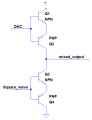
I am trying to make a cheap signal generator with variable frequency, amplitude and rise & fall time smaller than 100ns. I'm using MCU GPIO to produce square wave and DAC to change amplitude. I attach a schematic.
I've built the circuit, but the rise time is 500ns or something like that.I think the pull-up resistor is limiting the signal speed.But when i lower the value of pull-up, DAC is not able to produce required current.
Please share ideas how can i improve the circuit. Thank you")
I am trying to make a cheap signal generator with variable frequency, amplitude and rise & fall time smaller than 100ns. I'm using MCU GPIO to produce square wave and DAC to change amplitude. I attach a schematic.
I've built the circuit, but the rise time is 500ns or something like that.I think the pull-up resistor is limiting the signal speed.But when i lower the value of pull-up, DAC is not able to produce required current.
Please share ideas how can i improve the circuit. Thank you
Attachments
-
 40.1 KB Views: 14