 Facebook
 Google
 GitHub
 Linkedin
hello friends..
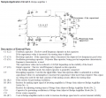
I often sees amplifiers using various capacitor arrangements for filtering the audio spectrum for passing specific frequency levels and I never knew how to change it according to our need. So to learn about it I thought of using a LA4440 amplifier circuit in bridge mode (which is capable of delivering 19W at the output) to drive a sub woofer. On looking at the datasheet I saw the description about the capacitors used in the circuit but I found it very hard to understand as I'm not good in electronics. So could anyone help me with the capacitor values & the method for its calculations?? I'm attaching the circuit and the description in the datasheet.
I often sees amplifiers using various capacitor arrangements for filtering the audio spectrum for passing specific frequency levels and I never knew how to change it according to our need. So to learn about it I thought of using a LA4440 amplifier circuit in bridge mode (which is capable of delivering 19W at the output) to drive a sub woofer. On looking at the datasheet I saw the description about the capacitors used in the circuit but I found it very hard to understand as I'm not good in electronics. So could anyone help me with the capacitor values & the method for its calculations?? I'm attaching the circuit and the description in the datasheet.
Attachments
-
 167.3 KB Views: 13
Last edited:


