Challenge of OLD TV(Sony KV 2192M3)

Thread Starter

ranatungawk

Joined Oct 30, 2008
226
G1 is negative with respect to the cathode. What is the Cathode voltage? If the Cathode was 56 volts and the G1 was 28 volts, it would be negative.

G1 is the control grid.
Thanks for replying me.

is the Cathode voltage G1 voltage ??? or how to find ti ? (schematic is attached into the thread). when it check with a DMM can we see (-) voltage?
 

JoeJester

Joined Apr 26, 2005
4,390
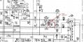
You will notice on your schematic, the cathodes have three different voltages, from approximately 150 to 175 Volts. The 200 V supply uses a voltage divider to supply the G1 voltage. The G1 Voltage of 28V is within 10 percent of a calculated voltage. Also note that the G1 voltage is more negative than the cathode voltages. If we placed a meter between the cathode and the G1, with the read lead on the G1, your meter would read negative 122 to neg 147 depending on which cathode you put the black lead.
 

R!f@@

Joined Apr 2, 2009
10,014
@JoeJester is correct.
With respective to the CATHODE, G1 will be negative.

Cathodes are connected to the RGB terminals which the amplifies video signal is fed.
Cathode produce the electrons that strike the phosphor screen producing the picture
 

Thread Starter

ranatungawk

Joined Oct 30, 2008
226
@JoeJester is correct.
With respective to the CATHODE, G1 will be negative.

Cathodes are connected to the RGB terminals which the amplifies video signal is fed.
Cathode produce the electrons that strike the phosphor screen producing the picture


Today i did the following testing but still i couldn't fix the issue

1. C704, C712, C851(22uf/250V) was replaced
2. All the Neck board resisters were checked and found OK
3. However R704 (470K) shows 520K & the R738 (680K) show 740K ------- Can this be a issue ?
4. I found positional voltages as below :
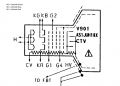
a. position mark as 1 on the neck board: 135V;

b. position mark as 2 on the neck board: 142V;
c. position mark as 3 on the neck board: 133V;
d. position mark as 4 on the neck board: 121V;
e. 200V on the diagram as ------------- 189V
f. 1000V on the diagram as ------------- 1008V
g. G1 as 28V
h. G2 as 360V

Are these voltage correct??? on the diagram there are another voltages ,aren't they ?
other than this , i checked the SCREEN variable resister, when it was rotated screen-brightness was change correctly (it seems to be OK)
G1 terminal was disconnected from the board. screen was too bright (Whiter) and the white strip disappears (or i couldn't see due to the brightness )

so what can i do next ...?
1a.JPG


JoeJester

Joined Apr 26, 2005
4,390
The 1000volt supply is divided to 200volts and the voltage you see on G1.

What color is the fourth band on those resistors? Gold is 5% tolerance and silver is 10% tolerance.

Better yet....take a picture and post it.
 
Last edited:

Thread Starter

ranatungawk

Joined Oct 30, 2008
226
The 1000volt supply is divided to 200volts and the voltage you see on G1.

What color is the fourth band on those resistors? Gold is 5% tolerance and silver is 10% tolerance.

Better yet....take a picture and post it.

"The 1000volt supply is divided to 200volts and the voltage you see on G1."

OK! but according to the schematic digram, voltages i found are wrong , aren't they ???
 

JoeJester

Joined Apr 26, 2005
4,390
Depends on the tolerance.

Can you put that TV on a channel you are authorized to receive and post a picture?

Do you have access to an oscilloscope to verify the signals are the proper pk-pk as seen on the schematic?

Are all the controls (bright, color, contrast, etc) set to mid level?

Did you fiddle with the sub-bright adjustment on the PCB?
 

Thread Starter

ranatungawk

Joined Oct 30, 2008
226
Depends on the tolerance.

Can you put that TV on a channel you are authorized to receive and post a picture?

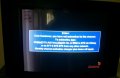
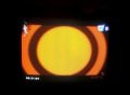
I have already post the in this thread, please watch them

Do you have access to an oscilloscope to verify the signals are the proper pk-pk as seen on the schematic?

Sorry, i'm not a professional technician and i don't have a OCR.

Are all the controls (bright, color, contrast, etc) set to mid level?

Yes! when they are changed screen respond correctly too

Did you fiddle with the sub-bright adjustment on the PCB?
didnt change any default settings on the PCB


Thank you very much for you guys support to me on this matter
 

R!f@@

Joined Apr 2, 2009
10,014
You test is not complete.
I said to put a resistor at G1 to GND...not to leave it open

Read the post carefully.
This Picture needs to be black to see the white strip.

3. However R704 (470K) shows 520K & the R738 (680K) show 740K ------- Can this be a issue ?
Need to know the color codes of these two R's
 

Thread Starter

ranatungawk

Joined Oct 30, 2008
226
You test is not complete.
I said to put a resistor at G1 to GND...not to leave it open

Read the post carefully.
This Picture needs to be black to see the white strip.
Need to know the color codes of these two R's
1. Yes its not completed (at the testing, i couldn't find a 1k/2w resister, can i put 3.3K 10W one ? ) i'll do it and let you know
2. This Picture needs to be black to see the white strip. --> i don't know what you need is this , i turn the screen black with the "screen VR" on the Neck card. then the screen got black totally and didnt see any white lines.
3. Colore bands and the schematic values are correct but cant remember the tolerance level. (ill let you know)

Other than these, do we have to check "horizontal sweep circuit / line scan circuit" side as highlighted early in this thread ?
 

Thread Starter

ranatungawk

Joined Oct 30, 2008
226
I'll do and let you know for sure
Do the test and come back.
If the resistor values are different I would replace them and check.
Then Proceed to other stages......
I'll do and let you know for sure. Thanks for the time you spend on this
 

Thread Starter

ranatungawk

Joined Oct 30, 2008
226
Do the test and come back.
If the resistor values are different I would replace them and check.
Then Proceed to other stages......


Thanks for all the advises you gave, finally i was able to fix it. it was a bad electrolytic cap as we expected! (C854 330Uf/25V).
when i tested it with a ESR meter it showed 220Uf/ 21 Ω ESR. it was replaced with a new one and TV screen was back to normal.

ok2.JPG Bad cap_Sony_1.JPG OK1.JPG
 
The plague of electronics... electrolytic capacitors.

Leaking aluminum electrolytics smell fishy, and may leave a black sticky residue around the base. If they overheat quickly, they may bulge on top. I have found that black leakage on the PCB and a fishy smell are much more likely.
 
Top