 Facebook
 Google
 GitHub
 Linkedin
Hello,
I have gotten an assignment at school to make a heating circuit,
also specified as a closed-loop control system of a temperature controller.
But I'm stuck and don't know how to approach it.
this is the assignment given:
I'll add the datasheet mentioned as attachments
Your assignment is to design and build the control system using an NTC resistor, a comparator, a potmeter, various resistors, and an electronic power switch.
For the heating element we will use a power resistor of 10 Ohms with power rating 3 Watt.
The datasheet for the NTC can be found here . The NTC you have has R/T characteristic 2904.
For the power switch we will use an N-FET STP16NF06 (click for datasheet).
Add a LED (+ resistor) to the output of your controller to check whether the output is switched on or off.
So I hoped that someone could help met out on where to start or to give an example of the circuit asked.
Some other things that are asked are:
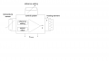
So, summarized in short: is there someone that can help me draw the circuit for this assignment? and I've also added an image of a circuit that was given in the assignment as example.
I have gotten an assignment at school to make a heating circuit,
also specified as a closed-loop control system of a temperature controller.
But I'm stuck and don't know how to approach it.
this is the assignment given:
I'll add the datasheet mentioned as attachments
Your assignment is to design and build the control system using an NTC resistor, a comparator, a potmeter, various resistors, and an electronic power switch.
For the heating element we will use a power resistor of 10 Ohms with power rating 3 Watt.
The datasheet for the NTC can be found here
. The NTC you have has R/T characteristic 2904.For the power switch we will use an N-FET STP16NF06 (click for datasheet)
.Add a LED (+ resistor) to the output of your controller to check whether the output is switched on or off.
So I hoped that someone could help met out on where to start or to give an example of the circuit asked.
Some other things that are asked are:
- Analyse your actuator: what power source do you need to heat it up to it’s maximum?
- What is the maximum supply voltage for the resistor?
- What is the maximum current through the resistor?
- Is the N-FET able to handle that?
- How can you use a potmeter to generate an appropriate voltage usable as setting?
- Analyse your sensor: find the R value vs T graph of your NTC.
- How can you convert the NTC resistance value to a voltage?
- How do you connect the inputs to your comparator?
- How do you connect the N-FET to the comparator?
- How are you going to supply power to the comparator?
- How do you connect the LED and its series resistor? What is the value for the resistor?
So, summarized in short: is there someone that can help me draw the circuit for this assignment? and I've also added an image of a circuit that was given in the assignment as example.
Attachments
-
537.4 KB Views: 2
-
325.8 KB Views: 1
-
 40.7 KB Views: 8


