CD4066 crosstalk

Thread Starter

Arjune

Joined Jan 6, 2018
234
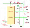
I have a problem with audio going from input to output with pops of audio when CD4066 switch is off by the 7555 timer. The audio input is less than 100 millivolts. I don't know if the cd4066 is faulty since I had it for over 20 years. It's a CMOS chip and I don't take any precautions with static when I handle it. I tried different gates on it but I still have the same problem. I think the data sheet recommends 10,000 ohms as the load and I have 47000 ohms. The input is coming from a mixer and the output is going to an amplifier. I am using a 9 volt battery as the power supply. The timer turns on the cd4066 for approximately 1 hour to transfer the line signal. The whole circuit only uses about 50uA. There is a 47 microfarad bypass capacitor for the power supply. The main reason I want to build the circuit is to use it as a sleep timer. I only have one of these chips and it's expensive on eBay so I can't try another one to see if the problem persists.
audio switch.png
 

crutschow

Joined Mar 14, 2008
34,283
A couple things to try:

A small capacitor from the output to ground (try 100pF or so).

An RC filter at the control input to slow down the signal.
Try 100k in series with 1μF to ground.

A nit -- Crosstalk usually refers to one audio signal getting into another.
What you are seeing is feedthrough from the control signal to the audio.
 
Last edited:

ronsimpson

Joined Oct 7, 2019
2,988
I think if you replace the 4066 with a toggle switch you will have a pop when you open/close the switch. I have seen this problem but it has been many years and I don't remember. Are the two 10uF caps good? (leaky) I think the pop is happening because the bias moves when you open/close the switch. Put a meter (dc volts) on pin 11. Does the dc voltage move 50mV when the switch changes?

The 4060 is made to work with signals in the gnd to Vcc range. (works best with a analog signal at 1/2 supply) You are using a signal at and slightly above/below gnd. Try adding two resistors. 47k from pins 10 & 11 to +9V. See if that helps. Bias at 1/2 supply. If your signal was 1V I think this would help but at 0.1V it may not help.
 
Last edited:

AlbertHall

Joined Jun 4, 2014
12,345
The input and output coupling capacitors are the correct polarity only if the input and output both have a negative DC voltage.
If the capacitors are the wrong way round they will be leaky and then the switching the '4066 will change the DC level making a pop sound.
 

Audioguru again

Joined Oct 21, 2019
6,673
I agree that you should switch the 4066 on and off slowly with an RC filter.
I worked with a high-end huge intercom system. In addition to switching the 4066 switches on and off a little slowly, it ramped down the audio level, switched, then ramped the audio level back up because audio has some positive peaks and some negative peaks that would cause POPs if passed suddenly.
 

Thread Starter

Arjune

Joined Jan 6, 2018
234
A couple things to try:

A small capacitor from the output to ground (try 100pF or so).

An RC filter at the control input to slow down the signal.
Try 100k in series with 1μF to ground.

A nit -- Crosstalk usually refers to one audio signal getting into another.
What you are seeing is feedthrough from the control signal to the audio.
I'm sorry I wasn't clear, the problem is not coming from the control of the 4066. There is some distorted feedthrough from input to output when the 4066 control is low. I am using non polarized capacitors for input and output. I tried 0.001uF from output to ground and it worked but then stopped working.
 

Audioguru again

Joined Oct 21, 2019
6,673
You are biasing the switch at 0V but you are feeding it with AC that goes above and below ground which is wrong. Instead you should bias the input and output of the switch at half the supply voltage so that its works properly with an AC input signal.
Your 10uF input capacitors pass earthquake extremely low frequencies. Why?
 

Attachments

Thread Starter

Arjune

Joined Jan 6, 2018
234
You are biasing the switch at 0V but you are feeding it with AC that goes above and below ground which is wrong. Instead you should bias the input and output of the switch at half the supply voltage so that its works properly with an AC input signal.
Your 10uF input capacitors pass earthquake extremely low frequencies. Why?
Thank U audio guru, your solutions of the bias worked. The capacitors are loaded with the 47k divider and would cut low-frequency response. I need at least 10 microfarads don't I?
 

Audioguru again

Joined Oct 21, 2019
6,673
10uF into 47k ohms produces -3dB at 0.34Hz which is something waving 3 times per second. Audio goes down to 20Hz but most good speakers have trouble below 40Hz. You could have used 0.22uF to feed 47k ohms and still pass frequencies that are lower than you can hear.
 

ronsimpson

Joined Oct 7, 2019
2,988
I need at least 10 microfarads don't I?
I hate to disagree with the AudioGuru but:
In this schematic R3 is for the 4066 when closed. V1 is the input signal. R6 is the next amplifier. (unknown value but likely 100k)
C4 and resistance makes the low block filter. As mentioned by two post there needs to be two (4) 47k resistors. Down side of C4 is (R1//R3 which is about 24K) and (R4//R5 which is 24k) And the two 24k are in parallel so 12K and through C1 the next amp has input impedance, unknown but I am saying 100k. (math in my head) That makes about 11k load. So the frequency is 10uf and 11k.
Then there will also be C1 & R6 roll off.

1587855961922.png
1587855865330.png
 

Audioguru again

Joined Oct 21, 2019
6,673
Yes, I forgot the the CD4066 is simply a switch without any buffering. Then the 10uF capacitor still passes all audio frequencies plus most earthquake frequencies. It does not pass the putt, putt, putt sound of an idling motorcycle.
 

Audioguru again

Joined Oct 21, 2019
6,673
My misunderstanding indicates that we have a logical challenge audio guru by Ron Simpson.
There is no challenge. The graph made by Ron Simpson has an additional output highpass filter with your 10uF output capacitor feeding a 100k ohm load which causes another -3dB cutoff at 0.16Hz which is 125 times lower than audible frequencies. His graph shows a total -3dB cutoff at about 3Hz which is about 6.6 times lower than you can hear. Therefore your 10uF coupling capacitor values are too big and will take a long time to charge.
Also, the putt, putt, putt of a motorcycle has many harmonic frequencies that you can hear. I can hear the rumble from jet airplane engines at takeoff from the airport that is 12km away from me. I hear the rumble because it also contains many audible harmonic frequencies.
 

Thread Starter

Arjune

Joined Jan 6, 2018
234
Audio Guru all I can hear from a motorcycle is putt putt putt and no harmonics. I cannot hear a jet airplane 12 km away and I don't believe I can hear any harmonics if I was closer. I've come to the believe that you may not be a human being but an alien with extrasensory perception that's why you disbelieve the reality of the 10 microfarad capacitor. I am a schizophrenic and I can understand the non-belief of reality. If you're dealing with the real world I believe Ron Simpson is correct and the resistors do add a loading factor. You are seeing the capacitor as independent of the resistors. I was wondering, the input and output of the 4066 is connected to ground when the switch is off right? My understanding was that the input and output was separated buy 100 megohms and it was not grounded. Maybe you're thinking that when the switch is on the 10 microfarad capacitors are isolated from a load because you're clairvoyant, thinking that they are a sole entity.
 
Last edited:

Audioguru again

Joined Oct 21, 2019
6,673
When the CD4066 switch is turned on then it is effectively a 100 ohm resistor from input to output. The four voltage divider resistors I recommended produce a resistance fed by the 10uF input capacitor of 47k/4= 11.75k ohms.
The formula for the -3dB cutoff frequency is 1 divided by (2 x pi x R x C)= 1.36Hz which is 15 times lower than the lowest frequency anybody can hear. The 100k output resistor has been added by Ron and is fed from your 10uF output capacitor. It reduces frequencies below 0.16Hz which is 125 times lower than anybody can hear. The 10uF output capacitor charges slowly when feeding 100k ohms to ground, 10uF x 100k x 5= 5 whole seconds for you to hear distortion after power-up until the capacitor is charged. Therefore the 10uF capacitor values are much too high.

When the switch is off then the input and output ARE NOT connected to ground, the switch is 100M ohms and the input and output are connected to the voltage divider resistors (at half the supply voltage) and to the input and output capacitors.

When the switch is on then the 10uF input capacitor feeds all four voltage divider resistors in parallel, 11.75k ohms, and passes frequencies as low as 1.36Hz which is much lower than you need and slows down charging when first powered up.
 
Top