Facebook
 Google
 GitHub
 Linkedin

Hello! First post here and I'm looking forward to many more 
As per the title, I (think) I know the circuit to control capacitor voltage discharge, a simple capacitor connected to + and gnd with a resistor tied around it on a switch. Switch is thrown and the cap begins to discharge.
I've done a few calculations using 9v power supply and a 220u capacitor. It seems a 50k resistor will have a time constant of 11 seconds. I think for my needs, that will be the longest time constant I would need. I intend on putting a 50k potentiometer to use for variability.
However, I'd like to throw and LED into the mix with a forward current of 25ma and forward voltage of 2.2v.
When the switch is open and the capacitor is fully charged, the LED should be at full brightness. When the switch is thrown, the LED will dim as the cap loses brightness. I assume an LED and it's limiting resistor would go between the cap and ground and the drain resistor would still go from 9v to ground? Does the addition of the LED and current limiting resistor affect the discharge time?
Also, is there any way to linearize the discharge time? The time constant is a measurement of discharge of ~63% of the voltage making appear logarithmic. Is there a way to smooth it out?
Thanks!
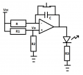
EDIT: Something like this, but with a switch between 9v and the time potentiometer (oops)

As per the title, I (think) I know the circuit to control capacitor voltage discharge, a simple capacitor connected to + and gnd with a resistor tied around it on a switch. Switch is thrown and the cap begins to discharge.
I've done a few calculations using 9v power supply and a 220u capacitor. It seems a 50k resistor will have a time constant of 11 seconds. I think for my needs, that will be the longest time constant I would need. I intend on putting a 50k potentiometer to use for variability.
However, I'd like to throw and LED into the mix with a forward current of 25ma and forward voltage of 2.2v.
When the switch is open and the capacitor is fully charged, the LED should be at full brightness. When the switch is thrown, the LED will dim as the cap loses brightness. I assume an LED and it's limiting resistor would go between the cap and ground and the drain resistor would still go from 9v to ground? Does the addition of the LED and current limiting resistor affect the discharge time?
Also, is there any way to linearize the discharge time? The time constant is a measurement of discharge of ~63% of the voltage making appear logarithmic. Is there a way to smooth it out?
Thanks!
EDIT: Something like this, but with a switch between 9v and the time potentiometer (oops)
Last edited: