 Facebook
 Google
 GitHub
 Linkedin
Hello,
Background:
I am working on a project in which I need construct a linear position measurement system using concentric capactive plates to calculate the linear position of the inner plate relative to the outer plate. The plates are constrained such that the only degree of freedom is along the Z axis (down the center of the capacitive tubes). The framework consists of PLA plastic and the capacitive plates consist of copper foil on a PLA support structure. Range of capacitance to be measured is between 4 and 40 pF. Capacitive shielding is located along the entire length of the cylinder at a separation distance of 50 times the spacing between the sensing plate and the ground plate. The capacitive plates are oriented such that the capacitance varies from maximum to minimum in a linear fashion.
Current prototype:
My current working version uses a 555 timer in astable multivibrator mode, see attached schematic. Note: RA and RB are not included on the schematic. They were experimentally determined once the initial PCB board was completed and are used for changing the range of frequencies output for a given capacitance range. These values are not immediately available to me, but I can add them next week if they are deemed necessary.
Current status:
The current version offers a repeatable resolution of 0.01" for a 2.5" total travel distance when the measurements are taken while the inner plate is held in a static position.
Current problem:
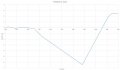
During smooth, fast, movements (2.5" in 0.1 second), the transient response of the circuit is not as predicted. Instead of a smooth curve from the initial point to the final point, the output always takes a sharp, immediate drop (corresponding to a sharp drop in output frequency) and then quickly approaches the final position, see attached plot. This is not an issue during very slow movements. Note on the plot that the step input occurs at the start of the plot and that the delay for 25ms is due to the physical characteristics of the actuation system, not the measurement circuit.
Can anyone offer an explanation for the behavior of this circuit and/or a method to rectify the negative spike during fast movement?
Thanks,
Jeremy
Background:
I am working on a project in which I need construct a linear position measurement system using concentric capactive plates to calculate the linear position of the inner plate relative to the outer plate. The plates are constrained such that the only degree of freedom is along the Z axis (down the center of the capacitive tubes). The framework consists of PLA plastic and the capacitive plates consist of copper foil on a PLA support structure. Range of capacitance to be measured is between 4 and 40 pF. Capacitive shielding is located along the entire length of the cylinder at a separation distance of 50 times the spacing between the sensing plate and the ground plate. The capacitive plates are oriented such that the capacitance varies from maximum to minimum in a linear fashion.
Current prototype:
My current working version uses a 555 timer in astable multivibrator mode, see attached schematic. Note: RA and RB are not included on the schematic. They were experimentally determined once the initial PCB board was completed and are used for changing the range of frequencies output for a given capacitance range. These values are not immediately available to me, but I can add them next week if they are deemed necessary.
Current status:
The current version offers a repeatable resolution of 0.01" for a 2.5" total travel distance when the measurements are taken while the inner plate is held in a static position.
Current problem:
During smooth, fast, movements (2.5" in 0.1 second), the transient response of the circuit is not as predicted. Instead of a smooth curve from the initial point to the final point, the output always takes a sharp, immediate drop (corresponding to a sharp drop in output frequency) and then quickly approaches the final position, see attached plot. This is not an issue during very slow movements. Note on the plot that the step input occurs at the start of the plot and that the delay for 25ms is due to the physical characteristics of the actuation system, not the measurement circuit.
Can anyone offer an explanation for the behavior of this circuit and/or a method to rectify the negative spike during fast movement?
Thanks,
Jeremy
Attachments
-
 22.9 KB Views: 72
 -
 53.1 KB Views: 55


