Facebook
 Google
 GitHub
 Linkedin
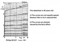
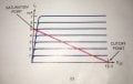
I have been told about characteristic curves like this for a while but have never fully understood where they come from. I don’t see them on the datasheets, although they have a similar one where Ic and Ib are switched, and my books don’t really explain where they come from. Is this something I need to draw myself? If so where do I get the information required? Is it through testing the transistor on a meter or doing some math? Is the load line something I draw? Thanks in advance.
Attachments
-
 568 KB Views: 35