Can distortion be lowered on budget sig. gens?

Thread Starter

oh_uh_okay

Joined Aug 24, 2025
98
For audio amplifier testing, a common criticism is that common, inexpensive AWGs (arbitrary waveform generator, or signal generators) cannot produce signals with low enough distortion to effectively measure audio devices.
For example, in this video, the tech measures the distortion of a common $150 Chinese sig. gen to be about 0.7%. On the other hand, the Heathkit IG-18 also in the video -- a device purpose-designed in the late 1960s for audio -- measures significantly better in OEM condition.
The vlogger improves the performance of the IG-18 further. Modders also have kits and projects to improve such vintage devices. Even since the magazine days.
So can budget, modern Chinese devices also be improved? I a have Koolertron DDS, same as the vlogger, and I might see potential in starting with the 5V power adapter.
Not sure about rest of the unit. Anyone tackle such a project?

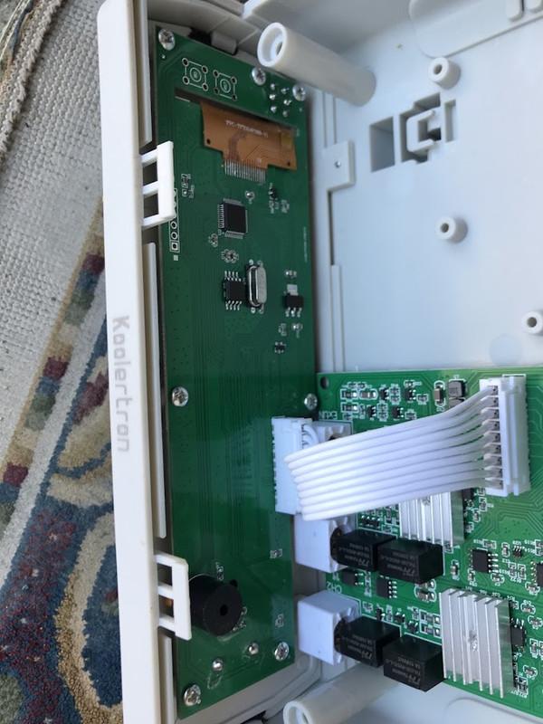
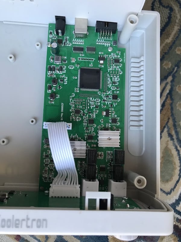
Inside the Koolertron :


MisterBill2

Joined Jan 23, 2018
28,419
OK, good resolution photos that do not show device type numbers AT ALL!! What I see is an instrument with an attractive PCB, and a LSI processor to drive the display.
None of that tells me about whet the circuit is or how it works, except that much of it is digital.

To discover anything about amplifier distortion you will meed a dual trace scopr to display both the input and the output of the amplifier at the same time. ALL of the differences in shape between the input and output , except the size, are from distortion.
 

crutschow

Joined Mar 14, 2008
38,859
You could use a low-pass filter on the output to reduce high frequency harmonic distortion products, but the filter frequency would need to adjusted to the test frequency.
On example for that is a state-variable (biquad) 2-pole, active-filter whose frequency can be tuned with a dual pot.

Edit:
Below is an example biquad circuit that allows adjustment of the rolloff frequency from about 1kHz to 20kHz with a ganged, dual 50kΩ pot (U4).
Audio-taper pots could be used to make the frequency adjustment more linear versus pot rotation.

The op amps should be a low distortion audio type such as the NE5532.

If you want to operate on just a single 5V supply, then you would need to use a low distortion amp designed for that, such as the OPA365 (single) and OPA2365 (dual) or OPA1656 (dual) / OPA1655 (single).
This, of course, would require AC coupling of the amps with an amp pseudo-ground at 1/2 the supply voltage.

You would adjust the filter to be about -6db down (0.5) at the test frequency.
That would reduce the harmonics by the frequency of each harmonic in sequence (i.e. -12dB for the second harmonic, -24dB for the third harmonic, etc.).
The amount this reduces the distortion of your signal generator will depend upon the amplitude and frequency of the harmonics generating the distortion.

1791751335294.png
 
Last edited:

ronsimpson

Joined Oct 7, 2019
4,840
The DDS generators have an interesting set of problems that analog generators do not have. (and the reverse is true)
If your DDS is truly 14 bit, then you will have 16384 levels. There should be distortion at that level that can't be beat without some filtering.
Also; the sign wave is built in a table. The length of the table is 2048. There might be 2048 bumps in your output, which adds distortion.
In a high end DDS there is a way to create a sign wave, using on short table, and get 4x the points. Probably this generator does not do that.
I know of some DDS, and I have designed some many decades ago, that use math to fill in many points in between the points in the table. To say it another way, a math engine can look at 8 points in the table and create 100 points in between the data points that are in the table. I am certain that is not happening here.

I know this is a terrible example but think of this wave form having 16,000 levers vertically and 2000 steps horizontally. This wave form has 8 vertically and about 70 horizontally.
1791744653809.png
 
Last edited:

MisterBill2

Joined Jan 23, 2018
28,419
Consider that "distortion" will cause a difference between the input waveform and the output waveform. So displaying DISTORTION will require comparison of the two waveforms. Any othere scheme, based on examining ONLY the output waveform, is based on THE ASSUMPTION THAT THE INPUT WAVE IS PERFECT.
That may not be the case!!
Most honest equipment makers provide at least their claimed performance data, which includes distortion levels under specific conditions. Unfortunately that information is only in the equipment manual, which is often not available to a second or third instrument owner/user.
Of course, for actual signal generators, the difference is between the output and the "perfect" sine wave, except for those generators that intend to produce/deliver a different waveshape. A square wave is simpler and a triangle wave can be much simpler.
 
Last edited:

MisterBill2

Joined Jan 23, 2018
28,419
For a signal generator, there have been "sinewave converters around since the end of tube-days. Some are much better than others, of course. One easy choice could be a tuneable resonant circuit. Another scheme would be simply a "Low Pass" filter after the signal generator. Set for above the signal frequency but below twice the signal frequency.
 

Thread Starter

oh_uh_okay

Joined Aug 24, 2025
98
I know of some DDS, and I have designed some many decades ago, that use math to fill in many points in between the points in the table. To say it another way, a math engine can look at 8 points in the table and create 100 points in between the data points that are in the table. I am certain that is not happening here.
Are you talking about OVERSAMPLING?
Not sure why the cheap Koolertron-type DDS's can't overperform with respect to THD. Most CD players, since the early 80s (including the 14-bit Philips models), were capable of:
Google AI notes:
Total Harmonic Distortion (THD) in a CD player's output stage typically ranges between 0.001% and 0.005% (-100 dB to -86 dB) for high-quality modern solid-state designs. Premium or audiophile-grade components can achieve even lower figures, sometimes hitting 0.0002% to 0.0005% (-114 dB to -106 dB), approaching the theoretical performance limits of the digital-to-analog converter (DAC) chips themselves.
 

atferrari

Joined Jan 6, 2004
5,030
Long ago I implemented a dual audio generator using some CD4xxx ICs. The sinusoidal output was filtered with MF100 SC filters controlled by the same PIC 18F micro, in charge of the generators.

Despite it being my first experience with SC filters, they worked remarkably well.
 

Reloadron

Joined Jan 15, 2015
7,958
My read on distortion consist of Harmonics, Hum and Noise. How are you measuring the distortion? Harmonics are generally the large amount and the hum and noise are the much lesser. with the hum and noise on the signal peaks and valleys. So my question becomes how are you measuring using what device as in do you have a distortion analyzer? My early days I used a HP 332A Distortion Analyzer.

Ron
 

Thread Starter

oh_uh_okay

Joined Aug 24, 2025
98
My read on distortion consist of Harmonics, Hum and Noise. How are you measuring the distortion? Harmonics are generally the large amount and the hum and noise are the much lesser. with the hum and noise on the signal peaks and valleys. So my question becomes how are you measuring using what device as in do you have a distortion analyzer? My early days I used a HP 332A Distortion Analyzer.
So that is an important issue: how is distortion being measured? And what TYPE of distortion (THD, IMD, etc) Further, is the distortion analyzer calibrated? Can you turst it?
Good distortion analyzers, even classic and vintage units, are not as economical (easy to design and mass produce???) as the DDS.
Anyone know of good, modern analyzer that can be had for the same price of the Koolertron ($150)?

This kit version is avail for $50 on Amazon and ebay:
https://s.alicdn.com/@sc04/kf/HTB1ECYdXUvrK1RjSspcq6zzSXXaU.jpg?avif=close&webp=close


Or you can take your chances with a vintage tube unit on ebay:


Reloadron

Joined Jan 15, 2015
7,958
What frequency range did you have in mind? Earlier I mentioned my early experience was using an HP 332A distortion analyzer. I am seeing them as low as $80.000 on Ebay. I see a distortion analyzer as something we either need or nice to have. If fo example we are calibrating various signal generators we likely need one. The Heathkit you posted should work fine for general applications as long as it covers the range you need. Damn, I miss the Heathkit stuff. :) Really a matter of your budget. Yes, I would use the Heathkit version and I prefer solid state. :)

Ron
 

Thread Starter

oh_uh_okay

Joined Aug 24, 2025
98
I Googled "dds signal generator schematic" and came back with some simple projects, including:

https://www.electronics-lab.com/project/dds-function-generator/

https://hackaday.com/2020/02/25/review-unnamed-chinese-dds-function-generator/

And this on, right here on AAC, based on an ad9833:

https://www.allaboutcircuits.com/pr...m-generator-analog-devices-ad9833-ATmega328p/

What's missing from these projects is their THD performance. So for the AAC project, what might the distortion specs be?
If one could obtain, say .05% THD for the default project, then I might decide to build one.
 

crutschow

Joined Mar 14, 2008
38,859
f one could obtain, say .05% THD for the default project, then I might decide to build one.
The AD9833 data sheet states it has a maximum harmonic distortion at a 6KHz output with a 25MHz clock, of -55dBc, which is about 0.18% distortion.
.05% may be a little unrealistic requirement for a synthesizer generator.
 

nsaspook

Joined Aug 27, 2009
16,493
The DDS generators have an interesting set of problems that analog generators do not have. (and the reverse is true)
If your DDS is truly 14 bit, then you will have 16384 levels. There should be distortion at that level that can't be beat without some filtering.
Also; the sign wave is built in a table. The length of the table is 2048. There might be 2048 bumps in your output, which adds distortion.
In a high end DDS there is a way to create a sign wave, using on short table, and get 4x the points. Probably this generator does not do that.
I know of some DDS, and I have designed some many decades ago, that use math to fill in many points in between the points in the table. To say it another way, a math engine can look at 8 points in the table and create 100 points in between the data points that are in the table. I am certain that is not happening here.

I know this is a terrible example but think of this wave form having 16,000 levers vertically and 2000 steps horizontally. This wave form has 8 vertically and about 70 horizontally.
View attachment 372143
DDS can be pretty good with the right algo.
https://github.com/Linux-Comedi/comedilib/blob/master/demo/ao_waveform.c

Phase shifting sine testing DSO X/Y using DDS
 
DDS can be pretty good with the right algo.
I agree, in some ways it is incredible. The frequency is rock solid. ( as in crystal )
The waveform is as good as you can draw it in memory. ( With limitations on how much memory. )
The ARB generators I have can draw very complex patterns.
Chanel-1 can modulate Chanel-2 in many complex ways. AM, FM, phase shift, etc.
In the high-end generators complex things are done to make the output look "analog" without looking digital. In a $10,000 generator they can afford complex things. In a $100 generator I know there are things that are not done.
 
The MF100 tuneable filters mentioned by ATF are good choices.
Since they require a clock frequency 50 or 100 times the cutoff frequency, a PLL multiplier will track the oscillator frequency
 
For a tech experimentor I would try a classic "LC" tuned resoant circuit. A smaller "VARIAC " or "POWERSTAT" serving as the inductance and switched capacitors for the coarse tuning control. Certainly a bit inconvenient, but no DC offset issues and at lower power levels no harmonic distortion. It would be the filter, not the generator.
 

Thread Starter

oh_uh_okay

Joined Aug 24, 2025
98
Hey folks, .... look, I get it ... many of your are bored and want to lead the discussion into other directions.... Let's get back to FUNDAMENTALS of this thread that I created.
About the alleged higher THD of the cheaper Chinese DDS sig. gens like the Koolertron, I don't own a THD analyzer so I have to rely on word of mouth or posted or vlogged experiments. Go back to my first post about Trevor's experiments, comparing the Heathkit IG-18 to a cheap, modern DDS.
If any one has high-end analyzer and can quickly test out a cheap DDS, much thx in advance!
 
Top