Facebook
 Google
 GitHub
 Linkedin
Hello all,
I have a couple of questions regarding circuit design, pretty sure I won't explain myself properly and thought so context might help.
I am in the process of adding quite a few things to my vehicle and I am not to keen on the idea of running signal/trigger wires all throughout the vehicle. Guaranteed I will forget something, want something changed or find something new that will need more cables.
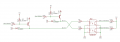
The plan is to have several relay/fuse boxes scattered around and I am trying to make a “Relay Driver” that will allow me to control the Relay’s through a CAN bus. I have attached a schematic of two of the five output/inputs.
https://www.swe-check.com.au/product/bussmann-15303-pdu-for-fuses-breakers-and-5-relays-dual-bus
The relay driver will have five outputs and each output will provide +12V for controlling a single relay. Each relay in the fuse box will also have a button wired in parallel with the relay driver allowing an override in the event of an issue. I was also hoping to get feedback from each output for fault detection and also if the relay was being overridden by the button.
The Questions
Current Limiting: Each relay draws about 100mA, the BC807 maximum current is 500mA so I was hoping to limit the current out to around 250mA. Without adding to much complexity to the circuit, what would be a good way to achieve this? Would a simple PTC fuse suffice?
Input Protection. I am not sure the 4.7K resistor will be enough to protect the optocoupler from the voltage spikes in vehicles. Should I be adding something like Zener or TVS Diodes?
The last question was... Am I on the right track? Have I done anything incorrectly or are there better ways to achieve the same result? This is all still very foreign, any comments or criticism would be greatly appreciated.
Thank you all in advance,
Alex
I have a couple of questions regarding circuit design, pretty sure I won't explain myself properly and thought so context might help.
I am in the process of adding quite a few things to my vehicle and I am not to keen on the idea of running signal/trigger wires all throughout the vehicle. Guaranteed I will forget something, want something changed or find something new that will need more cables.
The plan is to have several relay/fuse boxes scattered around and I am trying to make a “Relay Driver” that will allow me to control the Relay’s through a CAN bus. I have attached a schematic of two of the five output/inputs.
https://www.swe-check.com.au/product/bussmann-15303-pdu-for-fuses-breakers-and-5-relays-dual-bus
The relay driver will have five outputs and each output will provide +12V for controlling a single relay. Each relay in the fuse box will also have a button wired in parallel with the relay driver allowing an override in the event of an issue. I was also hoping to get feedback from each output for fault detection and also if the relay was being overridden by the button.
The Questions
Current Limiting: Each relay draws about 100mA, the BC807 maximum current is 500mA so I was hoping to limit the current out to around 250mA. Without adding to much complexity to the circuit, what would be a good way to achieve this? Would a simple PTC fuse suffice?
Input Protection. I am not sure the 4.7K resistor will be enough to protect the optocoupler from the voltage spikes in vehicles. Should I be adding something like Zener or TVS Diodes?
The last question was... Am I on the right track? Have I done anything incorrectly or are there better ways to achieve the same result? This is all still very foreign, any comments or criticism would be greatly appreciated.
Thank you all in advance,
Alex
Attachments
-
 16.2 KB Views: 11