Facebook
 Google
 GitHub
 Linkedin
Greetings,
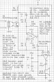
I am finally getting around to building the circuits found in my Forrest Mims books purchased on eBay. Currently I am building the AM Lightwave Transmitter circuit. In the process of discovery, I've found that the LM741 is dated and therefore it seems people point to the OPA134. So I have ordered some of those as I continue to experiment and build this circuit out and learn from doing so.
Question: The AM Lightwave Receiver circuit (shown in image) shows the use of an LM741 once again. Would this also be a suitable scenario to replace with the OPA134? Will there be a strange interaction using along with the LM386? I don't fully understand why both would have been used to begin with. Perhaps the LM741 is a preamp?

I really look forward to hearing some feedback (pun not intended... or maybe it is) from the community. Has anyone else ever built this circuit out and used it?
Cheers,
Coach
I am finally getting around to building the circuits found in my Forrest Mims books purchased on eBay. Currently I am building the AM Lightwave Transmitter circuit. In the process of discovery, I've found that the LM741 is dated and therefore it seems people point to the OPA134. So I have ordered some of those as I continue to experiment and build this circuit out and learn from doing so.
Question: The AM Lightwave Receiver circuit (shown in image) shows the use of an LM741 once again. Would this also be a suitable scenario to replace with the OPA134? Will there be a strange interaction using along with the LM386? I don't fully understand why both would have been used to begin with. Perhaps the LM741 is a preamp?
I really look forward to hearing some feedback (pun not intended... or maybe it is) from the community. Has anyone else ever built this circuit out and used it?
Cheers,
Coach