Hello, I joined the forum because I am looking for a bit of help with a SMPS that needs repair.
The board in question is a 715G2824-P03 which comes out of an Asus VE278 LED monitor. There are a few revisions of this type of PCB, (other revisions have inverter circuits included); this board omits the inverter section as it only needs a 6 pin connector for DC output to the LED backlight. In any case I believe the primary side circuits are basically the same or very similar throughout all revisions.
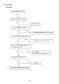
The problem with my board appears to be on the primary side. I have a schematic for a similar PCB, different revision, which I have been using to troubleshoot my board.
When I got the monitor, the primary MOSFET appeared to have blown up. I believe it was a STP10NK70. All I have done really is replace the MOSFET with a 2SK3797, as I did not have the ST part. Then I replaced the controller IC, LD7576 by Leadtrend. I also replaced a couple of resistors.
If I connect the PSU to the mains I get a voltage on Vcc (pin 6) of the LD7576, which appears to fluctuate between approx 11v and 14v. This is within spec according to the datasheet? But I don't know if it should be fluctuating or steady.
I checked the gate voltage on the MOSFET and most of the time it was zero, but it does sometimes go up to approx 2.5V then back to 0. I don't know what is happening, but for some reason it appears the LD7576 is not switching the MOSFET at all? In any case there appears to be 350V on the source but zero on the drain. So that is as far as the PSU wants to go; no output from primary side.
I was wondering if anybody on here could shed a little light on how this LD7576 primary circuit works and whether the 2SK3797 is a valid replacement for the STP10NK70 ?
Much appreciated.
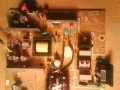
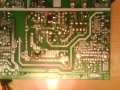
Included a schematic and a picture of both sides of the PSU.
The board in question is a 715G2824-P03 which comes out of an Asus VE278 LED monitor. There are a few revisions of this type of PCB, (other revisions have inverter circuits included); this board omits the inverter section as it only needs a 6 pin connector for DC output to the LED backlight. In any case I believe the primary side circuits are basically the same or very similar throughout all revisions.
The problem with my board appears to be on the primary side. I have a schematic for a similar PCB, different revision, which I have been using to troubleshoot my board.
When I got the monitor, the primary MOSFET appeared to have blown up. I believe it was a STP10NK70. All I have done really is replace the MOSFET with a 2SK3797, as I did not have the ST part. Then I replaced the controller IC, LD7576 by Leadtrend. I also replaced a couple of resistors.
If I connect the PSU to the mains I get a voltage on Vcc (pin 6) of the LD7576, which appears to fluctuate between approx 11v and 14v. This is within spec according to the datasheet? But I don't know if it should be fluctuating or steady.
I checked the gate voltage on the MOSFET and most of the time it was zero, but it does sometimes go up to approx 2.5V then back to 0. I don't know what is happening, but for some reason it appears the LD7576 is not switching the MOSFET at all? In any case there appears to be 350V on the source but zero on the drain. So that is as far as the PSU wants to go; no output from primary side.
I was wondering if anybody on here could shed a little light on how this LD7576 primary circuit works and whether the 2SK3797 is a valid replacement for the STP10NK70 ?
Much appreciated.
Included a schematic and a picture of both sides of the PSU.
Attachments
-
163.6 KB Views: 195
-
 226.8 KB Views: 56
 -
 283 KB Views: 26