Facebook
 Google
 GitHub
 Linkedin
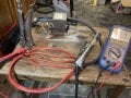
So im working on a basic microwave transformer converted to produce high current. I want to increase the current further by adding a second transformer in series and add power control maybe via a dimmer ok the primary.
so i need to be able to measure large currents and my clamp meter goes up to 100a only.
so my idea was to use my dc bench power supply with constant current, apply a known current (upto 2a), measure the voltage drop across my shunt and calculate the resistance.
This came to 1.3m ohm. (I did at 0.5a, 1a and 2a, all v similar)
next i attached the shunt to the high current secondary winding and measured the voltage drop here. (Primary connected to mains 240v AC supply). Voltage drop was 0.32v , which gives me a calculated current of 237a ( 0.32v/ 1.3m ohm)
seems reasonable so far, i was expecting something >100a….
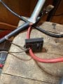
now i also made my shunt with 6 lengths of thick gague wire, firstly to minimise resistance and also so i could use my clamp meter on each piece and add up the current; 32a + 43a + 67a +50a + >100a + >100a = 392a !!
(>100 since my clamp meter maxes out at 100)
so im a bit puzzled now:
- current clamp readings much higher than calculated current. > 390 vs 230 amps???
I could only calibrate using dc supply since thats all i had… some sort of rms factor i needed to apply?
- the individual readings of each wire in the shunt were surprisingly different at 32 to >100. Appreciate they might be slightly different lenghts amd better or worse connected, but still surprised to see such a difference.
being able to measure the current fairly accurately is important for the application i want to use this for in welding (spot/tig welder…), so id appreciate any thoughts/feedback on this.
so i need to be able to measure large currents and my clamp meter goes up to 100a only.
so my idea was to use my dc bench power supply with constant current, apply a known current (upto 2a), measure the voltage drop across my shunt and calculate the resistance.
This came to 1.3m ohm. (I did at 0.5a, 1a and 2a, all v similar)
next i attached the shunt to the high current secondary winding and measured the voltage drop here. (Primary connected to mains 240v AC supply). Voltage drop was 0.32v , which gives me a calculated current of 237a ( 0.32v/ 1.3m ohm)
seems reasonable so far, i was expecting something >100a….
now i also made my shunt with 6 lengths of thick gague wire, firstly to minimise resistance and also so i could use my clamp meter on each piece and add up the current; 32a + 43a + 67a +50a + >100a + >100a = 392a !!
(>100 since my clamp meter maxes out at 100)
so im a bit puzzled now:
- current clamp readings much higher than calculated current. > 390 vs 230 amps???
I could only calibrate using dc supply since thats all i had… some sort of rms factor i needed to apply?
- the individual readings of each wire in the shunt were surprisingly different at 32 to >100. Appreciate they might be slightly different lenghts amd better or worse connected, but still surprised to see such a difference.
being able to measure the current fairly accurately is important for the application i want to use this for in welding (spot/tig welder…), so id appreciate any thoughts/feedback on this.
Attachments
-
 3.3 MB Views: 14