Calculation of flyback diode for PCB relay

Thread Starter

nikeklick

Joined Feb 21, 2018
10
Hello friends,

I am trying to design a printed circuit board (PCB) for a relay system at 115V.
I would be using two general purpose low power pcb relay RTE 24012.
However, i do understand that in order to prevent high voltage spikes, flyback diode is needed for the each relay.
May i ask how to do the calculation for the diode such that it would be able to suit the relay RTE24012 ?

Hoping to hear from you soon.

Thank you very much.
 

#12

Joined Nov 30, 2010
18,224
Anything in the 1N4000 series will do, but the 1N4007 is the same price as the others and it's rated for 1000 volts. No reason to buy a 50 volt diode when you can get 1000V for the same price.;)
 

DickCappels

Joined Aug 21, 2008
10,661
With what will you be driving the coils? If the coils are to be driven by switches or relay contacts spike suppression will rarely be needed.
 

ScottWang

Joined Aug 23, 2012
7,500
Anything in the 1N4000 series will do, but the 1N4007 is the same price as the others and it's rated for 1000 volts. No reason to buy a 50 volt diode when you can get 1000V for the same price.;)
I have another reason is because I can't identify which one is 1N4001 or which one is 1N4007, so just buy 1N4007 is better.
 

ebp

Joined Feb 8, 2018
2,332
If you want to know how to determine what is required:

Short answer: select a diode with a reverse voltage rating (often expressed as "peak inverse voltage", abbreviated "PIV") a bit higher than the power supply voltage and with a forward current rating greater than or equal to the relay coil operating current.

Long answer:
A relay coil is an inductor. The behavior of an inductor is that it "tries" to keep the current in the circuit constant. When you open the switch (transistor) that allowed the current through the coil to flow, at the instant the switch opens the inductor will keep the current at exactly the same magnitude and flowing in the same direction. Its stored energy will find some place to go - it doesn't "care" if it does it at 1 volt or 1000 volts.

Your relay operates at 12 volts and 34 mA (from the data sheet).
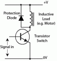
Consider Dodgydave's circuit at #2
First without the diode: If you turn off the transistor quickly, a current of 34 mA will still have to flow somewhere - same magnitude and same direction as it was just before turn-off. The voltage will rise until it reaches the breakdown voltage of the transistor. For a small transistor rated at say 40 volts, this voltage will probably be somewhere in the range of 45 to 60 volts. Let's say it happens at 50 V. The instantaneous peak power is 50 V x 34 mA = 1.7 watts. This isn't a lot and the transistor might survive or it might not. If that same transistor were driving a 12 volt relay that took 200 mA, the peak power would be 50 V x 0.2 A = 10 W. Now it looks a lot worse, and the transistor would likely be destroyed.

When you put the diode across the coil, it makes a path for the current. When the transistor turns off, the current (again, flowing in the same direction as before because the inductance forces it to) will cause the diode to conduct. The voltage at the collector of the transistor will rise to one "diode drop", around 0.7 volts, more positive than the power supply voltage. The peak current is still just 34 mA and the current slowly drops to zero as the stored energy is dissipated in the diode.

So - the diode has to handle a reverse voltage equal to the power supply voltage and it has to handle a peak current equal to the relay coil current. You need a diode rated at at least 12 volts and at least 34 mA. You won't be able to find an ordinary silicon PN diode rated that low. A 1N4148 diode or similar type has a rating far far higher than is required. You can certainly use a diode from the 1N400x family, but it is larger and a bit more expensive.

Using the diode in that way slows down the turn-off time of the relay, sometimes by several milliseconds. There are better ways to suppress the voltage spike for faster turn off.
You can actually almost always use a diode rated for current lower than the relay coil current.
Both of those matters take a whole lot more words, so ...
 
Last edited:

ScottWang

Joined Aug 23, 2012
7,500
@nikeklick, If you really want to know how to get a properly rated reverse voltage of diode, at least four times of the Vcc for relay would be better, I heard some people said that they met over 10 times reverse spike voltage of inductor product.
 

ebp

Joined Feb 8, 2018
2,332
No, you do not need PIV rating greater than the supply rail. You might add 20% to have a bit of margin. To suggest that you need a higher rating means that you don't understand the circuit.

An unclamped inductance can generate at spike of hundreds of volts, but it would be very unlikely with typical relay driver circuits because they are comparatively slow and some of the inductive energy is dissipated in the switch during turn-off time. The stored current flows through the diode in the forward direction, so there is no voltage spike. You can completely eliminate the need for any sort of clamping if you sufficiently slow the turn-off of the driver, but this usually requires more parts than a simple diode. A simple diode is sometimes a very unsatisfactory clamp because it slows the relay turn-off, which can be undesirable from a system timing point of view and/or because slow contact opening can be detrimental with regard to arc management.

If you had a very fast switch driving the relay in the circuit under consideration, a 1N4148 or a 20 PIV schottky diode would be superior to a 1N4007 because the forward recovery time of the diode would be much shorter. The 1N400x series is slow.
 

ericgibbs

Joined Jan 29, 2010
21,437
Hi Scott,
This LTSpice shows the diodes clamping effect.
The 1N4007 diode is used as it is a cheap diode, a diode with Vrev breakdown of > 25V would be OK.
Note the Vc plot.
The pulse current value thru the diode is the same as the current flowing in the relay coil
Eric

BTW: It is important to note that the power supply for the 5V must be a low impedance source capable of absorbing the back emf pulse.
Usually capacitor decoupling to 0V.
 

Attachments

Last edited:

ebp

Joined Feb 8, 2018
2,332
It is interesting to crank up the frequency (and/or inductance) for Eric's simulation and watch what happens. There will come a point where the inductor current will not drop fully to zero during the transistor OFF time. It will then begin to climb in staircase fashion, in this case probably limited by the 2N2222 current gain.
If you then change the 1N4007 to 2 or three in series, the influence on allowing higher voltage during "flyback" time will become apparent.

it all comes down to
δi/δt = V/L i in amperes, t in seconds, V in volts and L in henries
the differential of current with respect to time is equal to the voltage across the inductor divided by inductance
[Edit] - this ignores the influence of inductor resistance; for a relay resistance is significant; for the inductor in something like a flyback power converter it can mostly be ignored

This circuit does not return the stored energy to the supply rail - it dissipates it in the diode and the coil resistance. If you had a diode with zero voltage drop and a coil with zero resistance, the current would circulate forever.
 

ScottWang

Joined Aug 23, 2012
7,500
Thanks.
I bought many different numbers of 1n4000 series diodes in the beginning, but when I doing the experiments and touch the diodes more and more and then the id numbers will be loss its paint, so I can't identify their id numbers, that's why I only bought the 1N4007 now, and no anyone of 1N4001~4006, there is another reason that I don't have to check the id number, even they are all new, I can pick anyone to use it.
 

ScottWang

Joined Aug 23, 2012
7,500
Hi Scott,
This LTSpice shows the diodes clamping effect.
The 1N4007 diode is used as it is a cheap diode, a diode with Vrev breakdown of > 25V would be OK.
Note the Vc plot.
The pulse current value thru the diode is the same as the current flowing in the relay coil
Eric

BTW: It is important to note that the power supply for the 5V must be a low impedance source capable of absorbing the back emf pulse.
Usually capacitor decoupling to 0V.
And which diode that you will suggest for 25V?

I saw the other user guide of relay that they recommended to use zener diode and two times of rated voltage or higher.
 

ebp

Joined Feb 8, 2018
2,332
#12, I have no idea what that table is trying to say.

Diodes are far more complicated beasts than many people realize. I once had a great struggle with a smallish SMPS I was designing. I could not get the wretched thing to behave, and it looked like loop stability issues. I fussed and fumed and fiddled frequency factors (compensation) and it would not be tamed. I changed the ultrafast diode for one with, on paper, nearly identical recovery time & forward voltage and the bad behavior went away. I never did determine just what was going on.

here's a paper on recovery time models
https://www2.ee.washington.edu/research/pemodels/papers/simpforeverse.pdf

Cranky ol' Bob Pease, in his book Troubleshooting Analog Circuits (which I recommend, along with everything else he wrote (except for his bile against computers, which was downright silly) and that Jim Williams wrote) has some interesting stuff on diode forward conduction characteristics, diode leakage, using transistor junctions as diodes, etc.

Diode forward recovery is something rarely discussed. Lots has been written about reverse recovery time, which has become a very important issue with the rising prevalence and rising operating frequency of switch mode power supplies. Diode reverse recovery time can be a significant efficiency issue.
I think I once saw some data on trr for the 1N400x series, but I don't remember where. It's just accepted that they are slow (though their parents like to think of them as normal - see ON Semi datasheet)

When you get into fast and ultrafast PN junction diodes there usually is a performance penalty in going to unnecessarily high voltage rating. Higher voltage parts may be significantly slower. For example, in the FEP30xP series, parts rated up to 200 PIV have typical trr of 35 ns, those rated at higher voltage are have trr of 50 ns. In silicon schottky diodes, higher reverse voltage rating goes with higher forward voltage.
 

ebp

Joined Feb 8, 2018
2,332
Which diode will you suggest?
The 1N4007 is quite acceptable for any relay that requires up to about 3 A coil current. Obviously it isn't suitable for a supply rail more than 1000 V, but I think relays with 1000 V coils are ... rare.

I use 1N4148 or similar diodes for PCB-mount relays. The switching speed is better, but this rarely really matters at all with relays. I use them because they can be bent to 0.3" lead spacing for through-hole, which is a better physical fit match for small relays. If I had 1N400x elsewhere on the board and no other 1N4148 types, I'd use the 1N400x for the relays just to save a line on the bill of materials. In SMD I've used dual transistors in the small 6-pin package whose designation I can never remember. I use one transistor to drive the relay and one as a diode. Saves board space & placement cost (I've never done anything built in high volume, so it is often the case that placement of parts can cost considerably more than the parts).

Zeners and other methods are a better choice for power relays so they drop out faster.
 

Thread Starter

nikeklick

Joined Feb 21, 2018
10
If you want to know how to determine what is required:

Short answer: select a diode with a reverse voltage rating (often expressed as "peak inverse voltage", abbreviated "PIV") a bit higher than the power supply voltage and with a forward current rating greater than or equal to the relay coil operating current.

Long answer:
A relay coil is an inductor. The behavior of an inductor is that it "tries" to keep the current in the circuit constant. When you open the switch (transistor) that allowed the current through the coil to flow, at the instant the switch opens the inductor will keep the current at exactly the same magnitude and flowing in the same direction. Its stored energy will find some place to go - it doesn't "care" if it does it at 1 volt or 1000 volts.

Your relay operates at 12 volts and 34 mA (from the data sheet).
Consider Dodgydave's circuit at #2
First without the diode: If you turn off the transistor quickly, a current of 34 mA will still have to flow somewhere - same magnitude and same direction as it was just before turn-off. The voltage will rise until it reaches the breakdown voltage of the transistor. For a small transistor rated at say 40 volts, this voltage will probably be somewhere in the range of 45 to 60 volts. Let's say it happens at 50 V. The instantaneous peak power is 50 V x 34 mA = 1.7 watts. This isn't a lot and the transistor might survive or it might not. If that same transistor were driving a 12 volt relay that took 200 mA, the peak power would be 50 V x 0.2 A = 10 W. Now it looks a lot worse, and the transistor would likely be destroyed.

When you put the diode across the coil, it makes a path for the current. When the transistor turns off, the current (again, flowing in the same direction as before because the inductance forces it to) will cause the diode to conduct. The voltage at the collector of the transistor will rise to one "diode drop", around 0.7 volts, more positive than the power supply voltage. The peak current is still just 34 mA and the current slowly drops to zero as the stored energy is dissipated in the diode.

So - the diode has to handle a reverse voltage equal to the power supply voltage and it has to handle a peak current equal to the relay coil current. You need a diode rated at at least 12 volts and at least 34 mA. You won't be able to find an ordinary silicon PN diode rated that low. A 1N4148 diode or similar type has a rating far far higher than is required. You can certainly use a diode from the 1N400x family, but it is larger and a bit more expensive.

Using the diode in that way slows down the turn-off time of the relay, sometimes by several milliseconds. There are better ways to suppress the voltage spike for faster turn off.
You can actually almost always use a diode rated for current lower than the relay coil current.
Both of those matters take a whole lot more words, so ...
@ebp i am thinking of using SMD diode instead. Do you have any recommendations ? In order to have faster turn-off time of the relay, would be advisable to use zener or schottky diode ?
 
Top