Facebook
 Google
 GitHub
 Linkedin
Howdy
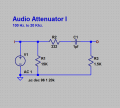
Recently I was trying to record a line-level signal into my phone input jack, and of course the level was too loud. I found a very good video (YouTube link) that provides a simple passive resistor circuit to drop the level.
How can I calculate the voltage drop that is happening via that 330ohm resistor?
Here is the circuit:

This almost looks like the normal voltage divider circuit but I'm not entirely sure. Would the 330ohm resister be R1 and the 1.5kohm resistor be R2, such as in this calculator? http://www.ohmslawcalculator.com/voltage-divider-calculator
How important are the values for the resistors to ground? What happens if I start modifying those?
Thanks for any insight
Recently I was trying to record a line-level signal into my phone input jack, and of course the level was too loud. I found a very good video (YouTube link) that provides a simple passive resistor circuit to drop the level.
How can I calculate the voltage drop that is happening via that 330ohm resistor?
Here is the circuit:
This almost looks like the normal voltage divider circuit but I'm not entirely sure. Would the 330ohm resister be R1 and the 1.5kohm resistor be R2, such as in this calculator? http://www.ohmslawcalculator.com/voltage-divider-calculator
How important are the values for the resistors to ground? What happens if I start modifying those?
Thanks for any insight