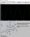
I took the class AB amplifier circuit from: https://www.electronics-tutorials.ws/amplifier/class-ab-amplifier.html
Anyways, the website states that the power output (to the 16 ohm load) is about 1 watt.
How is this calculated? I tried ohms law by doing 12V divided by 1K (r3) times 12 and I don't even get 1/2 that value.
Also, if I add emitter resistors in series on tip31 and tip32 transistors (like how R4 is connected to the 1st transistor, then how would those values determine the wattage output?