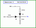
Calculate the current values in this diagram (ASSUMING IDEAL DIODES)

Thread Starter

Mojo Pin__

Joined Apr 13, 2019
83
Hello again,

Here is another exercise if you want to understand this better.
Calculate the voltage Vn at the node.
thank you for your initial message and this follow up one, I will definitely have a go at this tonight, thank you!
 

Thread Starter

Mojo Pin__

Joined Apr 13, 2019
83
Hello again,

Here is another exercise if you want to understand this better.
Calculate the voltage Vn at the node.
Ok this one is tougher, if I had to guess I would say both diodes are forward biased but I don't know how to calculate the values for current or voltage. Is there a technique to this one I should study?

Thanks!
 

MrAl

Joined Jun 17, 2014
13,761
Ok this one is tougher, if I had to guess I would say both diodes are forward biased but I don't know how to calculate the values for current or voltage. Is there a technique to this one I should study?

Thanks!
Hi,

You could remove each diode one at a time and see which one causes the highest voltage at Vn.
Then, put the removed one back in and see if it is forward biased. If it is, then it simplifies into a three resistor circuit with no didoes (both conducting).
 

MrAl

Joined Jun 17, 2014
13,761
Hello again,

A more interesting and deterministic way to handle this is to make each diode a current source with equation:
Id=Is*e^(19*Vd-1)

and then solve for the two diode drops.

It's a bit hectic and i think there is only a numerical solution possible, but it's worth doing once. The results are exact in as far as the number cruncher you use and the choice of Is. Is=10e-9 is a good choice for example. With that Is the node voltage comes out to 11.611 volts just for reference.
It is a little rewarding to see the exact voltages come out of the equations without assuming anything else.
 

Thread Starter

Mojo Pin__

Joined Apr 13, 2019
83
Hello again,

A more interesting and deterministic way to handle this is to make each diode a current source with equation:
Id=Is*e^(19*Vd-1)

and then solve for the two diode drops.

It's a bit hectic and i think there is only a numerical solution possible, but it's worth doing once. The results are exact in as far as the number cruncher you use and the choice of Is. Is=10e-9 is a good choice for example. With that Is the node voltage comes out to 11.611 volts just for reference.
It is a little rewarding to see the exact voltages come out of the equations without assuming anything else.

Thank you so much for your explanation, I can see the trick to it now. pretty tough to see right away.
 

MrAl

Joined Jun 17, 2014
13,761
Thank you so much for your explanation, I can see the trick to it now. pretty tough to see right away.
Hi,

Oh you are welcome and if i get a chance maybe i'll show the solution using the diode model. It's so cool how it works. It looks really nuts at first with all the exponentials of exponentials, but then the solution comes out neatly. Alternately using a multivariable numerical solver the solution comes out pretty easy.
 

MrAl

Joined Jun 17, 2014
13,761
Hello again,

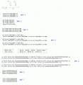
Here is a complete worked solution for a three diode circuit. The circuit and equations are shown in the attachment.

The narrative goes like this...

First note that in the equations the circuit voltages are:
E1=V1, E2=V2, E3=V3

SET 1 is the set of equations for the three diode models. I1 is current in D1, I2 is current in D2, I3 is current in D3. Vd1 is the voltage across D1, Vd2 is the voltage across D2, and Vd3 is the voltage across D3.
We use the same diode model for all three so Is and NVT are the same for all three. The voltage for each one is different and the current for each one is different so we use three different values for the diode voltage and the diode current.
The values used for the diode models are roughly the same as for a 1N4001 diode so if you do a simulation you will see values for current and voltage approximately the same as for that kind of diode.

SET 2 is the set of equations that equate the voltage drops in each diode string to the output voltage Vo1.
The fourth equation is for Vo1 itself which is the sum of all three diode currents times R4.

SET 3 is the same set just with the fourth equation above substituted for all Vo1 in the first three of SET 2.

SET 4 is the same set as SET 3 with all currents I1,I2,I3 replaced with their respective diode currents using the diode models of SET 1.

In the blocks that follow, the values for the diode models and for all the components and voltage sources are shown.

SET 5 is the same as SET 4 but with all those values in the blocks substituted for the respective component symbols.

SET 6 is after using a multivariable numerical solver to solve the equations for SET 5 for all three diode voltages.

SET 7 uses the solutions for all three voltages to calculate all three currents using the diode models.

There are other ways to solve these equations but this is the most straightforward. If you run into a problem that the numerical solver can not handle then you have to try to eliminate one of the variables from two sets of two equations and then try to solve for two variables, then go for the three variable later. Sometimes you can just solve for one part of the equation in some term and substitute that into another equation and try to solve that way. I'll defer this solution for another time as it can get hectic with the exponentials.

The equations and solutions shown should be accurate but you should do this yourself too.

Note this could also be an exercise in trying to get all three diode currents roughly the same value by setting the voltages E1, E2, E3, where each current is around 10ma.
 

Attachments

Last edited:

Thread Starter

Mojo Pin__

Joined Apr 13, 2019
83
Hello again,

Here is a complete worked solution for a three diode circuit. The circuit and equations are shown in the attachment.

The narrative goes like this...

First note that in the equations the circuit voltages are:
E1=V1, E2=V2, E3=V3

SET 1 is the set of equations for the three diode models. I1 is current in D1, I2 is current in D2, I3 is current in D3. Vd1 is the voltage across D1, Vd2 is the voltage across D2, and Vd3 is the voltage across D3.
We use the same diode model for all three so Is and NVT are the same for all three. The voltage for each one is different and the current for each one is different so we use three different values for the diode voltage and the diode current.
The values used for the diode models are roughly the same as for a 1N4001 diode so if you do a simulation you will see values for current and voltage approximately the same as for that kind of diode.

SET 2 is the set of equations that equate the voltage drops in each diode string to the output voltage Vo1.
The fourth equation is for Vo1 itself which is the sum of all three diode currents times R4.

SET 3 is the same set just with the fourth equation above substituted for all Vo1 in the first three of SET 2.

SET 4 is the same set as SET 3 with all currents I1,I2,I3 replaced with their respective diode currents using the diode models of SET 1.

In the blocks that follow, the values for the diode models and for all the components and voltage sources are shown.

SET 5 is the same as SET 4 but with all those values in the blocks substituted for the respective component symbols.

SET 6 is after using a multivariable numerical solver to solve the equations for SET 5 for all three diode voltages.

SET 7 uses the solutions for all three voltages to calculate all three currents using the diode models.

There are other ways to solve these equations but this is the most straightforward. If you run into a problem that the numerical solver can not handle then you have to try to eliminate one of the variables from two sets of two equations and then try to solve for two variables, then go for the three variable later. Sometimes you can just solve for one part of the equation in some term and substitute that into another equation and try to solve that way. I'll defer this solution for another time as it can get hectic with the exponentials.

The equations and solutions shown should be accurate but you should do this yourself too.

Note this could also be an exercise in trying to get all three diode currents roughly the same value by setting the voltages E1, E2, E3, where each current is around 10ma.

This is fantastic, seriously thank you for taking the time to post this, gonna show it to my class mates too!
 

MrAl

Joined Jun 17, 2014
13,761
This is fantastic, seriously thank you for taking the time to post this, gonna show it to my class mates too!
Hi,

Ok sure you are welcome.

Just a few extra notes...
1. You can solve for all three currents I1, I2, I3 first in SET 3 if you like that means you only have to insert the three diode models once.
2. Also, you can include the diode series resistance Rs by adding it in series with the respective series resistors already there, then calculate everything the same, then add the voltage across each Rs to the calculated diode voltages and that becomes the actual diode voltage drop.
The inclusion of this resistor at 10ma is very slight however adding only about 1.5mv to each diode voltage. At 100ma it would be about 15mv.
3. You can also add leakage resistance by placing a high value resistor in parallel with each diode before writing any equations. The equations get more complicated but the numerical solver finds the final results in the same manner. In one of my circuit simulators they use a value of 10 megohms for the leakage resistance but you can adjust that by looking at the data sheet for the diode you use.
4. NVT in the text is N*VT where N is the ideality factor and VT is the thermal voltage.
 
Top