By using LM317T regulating IC i want to get an regulated 9volt DC output

Thread Starter

Sivalie kohkoh Samba

Joined Oct 13, 2017
4
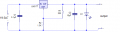
By using regulating IC LM317 I had wanted to get an output of 9volts Dc by inputting 19.54DC as shown by the configuration below

upload_2017-11-9_4-1-45.png

This configuration gave an output of 7.54 volts DC. But yesterday I changed the electrolytic capacitor which was 10µF 25v to 3300µF 35v and I get 8.61 volts DC output, except that the LED died few seconds during the process. I want to know what component to change; the component value or the component it self to get an output of 9volts. And also if my circuit diagram is correct for this job. Thank you
 

Attachments

Bordodynov

Joined May 20, 2015
3,179
You need current and not voltage. On the Internet and in this forum you will find current generators on the LM317. The main thing is to know what current is needed for the normal operation of the LED. I know a couple of cases when the LEDs are connected directly to the voltage source. In one case, a $ 30 LED burned out.
 

AlbertHall

Joined Jun 4, 2014
12,346
I think the circuit is designed to supply 9V to some other circuit and the LED is just to indicate that it is on.
If this is the case then the problem is that you do not have a resistor in series with the LED to limit the current, about 470Ω would do do the job.
Without this resistor the LED will draw a large current and drag down the output voltage as you saw. Also this will kill the LED as you also saw/
 

Thread Starter

Sivalie kohkoh Samba

Joined Oct 13, 2017
4
Why?
10μF is quite adequate for most applications.
using the 10uF gave an output of 7.54v and i needed an out of 9v

I calculate the expected output voltage as 8.3V so you may want to increase the 1.3K to 1.4K.
ok, i will do just that thank you

ok, thank you all for your help, i will get on to you again:)
 
Last edited by a moderator:

Thread Starter

Sivalie kohkoh Samba

Joined Oct 13, 2017
4
Hello guys, i have finally got a result which i would like to share.
upload_2017-11-15_14-27-24.png
instead of using the 220ohm resistor, i used 200ohm, but i could only lay hand on 100ohm resistor so selected two resistor of 100ohm each and connected them in series and i also change he C1 (0.1uF) to 3300uF 35v capacitor and C2 remain the 10uF and i connect the LED series with 470ohm resistor. So my output result was 9.47v DC.
Thank you all for your help
 

Attachments

Audioguru

Joined Dec 20, 2007
11,248
Calculations from the 555 datasheet:
1) 1.25V/200 ohms= 6.25mA.
2) 6.25mA x 1300 ohms= 8.125V.
3) 8.125V + 1.25V= 9.375V plus 0.065V for ADJ pin current= 9.44V but it could be a little higher or lower.

Your schematic still wrongly shows an LED shorting the output of the supply. The LED must have a resistor in series with it.
 
Top