BUNKER HILL SECURITY 120 Lumen Solar Motion Security Light Modification

Thread Starter

Kimball31

Joined Dec 13, 2021
4
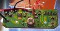
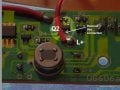
Similar to this post from 2013, Bunkerhill Security Light Modification I want to modify the light to disable the (low light) always-on-after-dark feature. I only want the motion activated (high, 120 lumen) light feature. The circuit board has been redesigned. The led array says 2016.06, and 2018 copywriter on the owners manual. I'm hoping like the older model I can remove/disable a resistor or component to disable the always-on-after-dark feature.

The unit is:
  1. Brand: BUNKER HILL SECURITY
  2. Model: 120 Lumen Solar Motion Security Light
  3. 20 SMD LED array
  4. 3.2v, 600mAh Lithium Ion Batttery
  5. White SKUs: 64732, 64733
  6. Black SKUs: 64736, 64735
  7. circuit board number is: DG606a

I measured the output for the low-mode (always-on) voltage at 2.57v, and the high-mode voltage at 2.77v. But I'm not certain the unit was fully charged.

If you has done this can you tell me how you did it?
Any idea where to look for find a schematic? There isn't one in the owners manual.

How can I temporarily disable the motion sensor so I can do some testing? I tried electrical tape over the sensor but that did not seem to work. I kept going into high-mode when I move.

20211214_162125.jpg

20211214_161844.jpg

20211214_155012.jpg

20211214_154850.jpg
 

Tonyr1084

Joined Sep 24, 2015
7,899
You can create a schematic from the printed circuit. Will need a clearer picture, and underneath the PIR (Passive Infra Red) motion sensor we have no way of seeing what the circuitry is. No clear identification of what the PIR is or the 8 pin chip on the board. But we'll give it a college try.
 

sghioto

Joined Dec 31, 2017
5,388
SW8183 is a solar LED lamp driver 2.5V-5V lithium batteries. SW8183 output current is adjustable 3W, 1A .
From what I can see on the PCB it appears to wired similar to the schematic below. Rs controls the amount of current through the LED from this formula: 1639619401117.png I suspect Rs is part of the Q1 and Q2 circuit but without further details on the schematic it's hard to tell for sure.
Can you trace out the paths and draw up a schematic or as you mentioned better photos?

https://xkw364362808.sell.everychin...thium-batteries-sw8183-output-current-is.html

1639619230412.png
 

Tonyr1084

Joined Sep 24, 2015
7,899
The latest picture is better. However, if you can move those wires so we can see where some of the traces underneath actually go, that would help a little. And if you can see under the PIR (Passive Infra Red) detector (BS 412) that, too, will help decipher the schematic.
 

Thread Starter

Kimball31

Joined Dec 13, 2021
4
Here's what I can see of the circuit board. Several connections go under components (shown as a blue line on the drawing), so I can't trace where they go. Any suggestions on how to determine what's going on under the RIP and 8183 chip?

If I need to remove RIP and 8183 to trace underneath, perhaps I should try remove the RS resistor first to see if that is in fact the low-light always-on part of the circuit. What are your thoughts on that?GC606a-LAYOUT.jpg

Thanks for the help and suggestions!
 

sghioto

Joined Dec 31, 2017
5,388
The RS resistor controls the current through the LEDs and its placement on your drawing is consistent with the schematic in post #5. M1 is a P channel mosfet that probably controls the LEDs when motion is detected via the PIR Out and Q1. That leaves Q2 which I think is the low light driver for the LEDs.
I would remove Q2 or if possible just cut the trace from the top pin of Q2 to the red LED wire you labeled L+.
 
Last edited:

Thread Starter

Kimball31

Joined Dec 13, 2021
4
sghioto, Removing Q2 worked. Thank you so much for your suggestion.

What I did was to un-solder the tab on Q2 that goes to L+. I've tested it for a couple of nights now and it does exactly what I want. The motion activated bright-light come on when you walk into view, and the low-light always on after dark feature has been disabled (stays off).

It it helps anyone, here is a picture of the connection I removed.
 

Attachments

Top