Building a discrete multi-stage guitar amp

Thread Starter

blah2222

Joined May 3, 2010
582
The first part of your sentence is correct, but are you sure about the second part?

The guitar pickup waveform is AC +/- in reference to ground. If we are talking about the same JFET circuit it is a single supply circuit which requires its input to always be above ground? Or have I missed something?
The device is a depletion-mode JFET and has a pinch-off voltage of around -3 to -4 V that Vgs has to stay above to operate. As long as Vds is above Vgs - Vpinch it will be operating as an AC amplifier.

I too think that it should be coupled through a capacitor in case of a DC bias...
 

Audioguru

Joined Dec 20, 2007
11,248
The gate of the Jfet draws no current and the 1M resistor and/or the magnetic pickup sets the gate at 0VDC with or without an input coupling capacitor.

With no gate-source voltage then the Jfet draws drain-source current which causes a positive voltage to appear at the source which reduces the drain-source current and automatically adjusts the bias.
 

Thread Starter

blah2222

Joined May 3, 2010
582
Thanks blah2222 and Audioguru for the explanation. :)
Np

Quick question regarding the 30 Hz coupling using the 4.7uF. Is that output coupling capacitor value calculated based on what the load and drain resistors are and what is needed for the 30 Hz coupling?

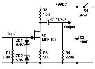
For instance given this amplifier:


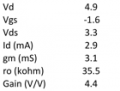
Based on my wired measured Q-point with a meter, I calculated it's small-signal parameters below.

So, what exactly is the RC circuit that the 4.7 uF capacitor is sees to create the 30 Hz filter?

I'm seeing R3 (560) in series with ro (35.5k) between capacitor +ve and ground, R2 (1.5k) between capacitor +ve and ground, and R4 (220k) between capacitor -ve and ground. (image below)

The resistance that the capacitor sees is (35.5k + 560)||(1.5k) + 220k ~= 221k

\(f_{3dB} = \frac{1}{2\pi (221k)(4.7u)} = 0.15 Hz...\)

Without R4 it becomes:

\(f_{3dB} = \frac{1}{2\pi (1.44k)(4.7u)} = 23.5 Hz\)

Which looks about right... Any thoughts?
 

Attachments

Last edited:

Audioguru

Joined Dec 20, 2007
11,248
The 4.7uf capacitor will cause 20Hz to be at -3dB when it couples a total resistance of 1700 ohms.
The output impedance of the Jfet preamp is 1.5k (R2) and its load should be 5 times to 10 times higher to avoid signal loss. Then with a load of 15k the capacitor should be 0.53uF for a 20Hz cutoff frequency or should be 0.36uF for a 30Hz cutoff frequency.
 

Thread Starter

blah2222

Joined May 3, 2010
582
The 4.7uf capacitor will cause 20Hz to be at -3dB when it couples a total resistance of 1700 ohms.
The output impedance of the Jfet preamp is 1.5k (R2) and its load should be 5 times to 10 times higher to avoid signal loss. Then with a load of 15k the capacitor should be 0.53uF for a 20Hz cutoff frequency or should be 0.36uF for a 30Hz cutoff frequency.
I see.

So, without excluding any resistances, what is the actual RC filter for this example that I presented? Aren't R3, R4, and ro (of JFET) players as well?

Cheers,
JP
 

Audioguru

Joined Dec 20, 2007
11,248
So, without excluding any resistances, what is the actual RC filter for this example that I presented? Aren't R3, R4, and ro (of JFET) players as well?
R3 is not part of the output highpass filter.
The output resistance of the Jfet is just R2. R4 is parallel with the load resistance and they are in series with R2.
 
Top