Build a circuit that is a variable timer(NE555P) in seconds It has a start state with two LED's.

WBahn

Joined Mar 31, 2012
33,068
Help. Tried several NE555P circuits from online posts but can't get any to work, well except one that partly worked.

I basically need help understanding from a beginners point of view, the only issue I have seen consistently is all tutorials talk as if you have a grounding in electronics or building, I have neither.

What I want to do is build a circuit that is a variable timer in seconds
It has a start state with two LED's, A red one that is lit and green one that is unlit.
Press a button, the Red LED goes out
After the specified time, the Green LED lights up

IF at any point in the button press the button is released during the time to wait, the timer resets back to 0 and user has to press the button again and start the holding process again.

Once the timer has elapsed, the Green LED lights up and the button can be released, the timer then resets for next press.

Can someone point me in the right direction on how to do this? I have about 60 NE555P chips and want to make 20 of these timers for a game.
Since you have a specific application in mind, let's start with some key issues there.

How long is the "specified time" that you are talking about?

Does this specified time need to be adjustable? Or is it permanently fixed?

How accurate does it need to be? In other words, if it should be 10 s, how close to 10 s does it have to be?

How precise does it need to be? In other words, if it should be 10 s, is it more important that all 20 be 10 s, or that all 20 be the same, even if they are not particularly close to 10 s?

Answers to these questions will go a long way in determining whether a 555-based solution is reasonable to begin with.
 

Thread Starter

damnucircuit

Joined Aug 12, 2022
20
Since you have a specific application in mind, let's start with some key issues there.

How long is the "specified time" that you are talking about?

Does this specified time need to be adjustable? Or is it permanently fixed?

How accurate does it need to be? In other words, if it should be 10 s, how close to 10 s does it have to be?

How precise does it need to be? In other words, if it should be 10 s, is it more important that all 20 be 10 s, or that all 20 be the same, even if they are not particularly close to 10 s?

Answers to these questions will go a long way in determining whether a 555-based solution is reasonable to begin with.
I am looking at a selectable dime delay, I have some rotary switches that would work with this in mind.

Times of 5, 10, 20, 30 seconds accuracy within 1 second I figure is imperceptible.

I have seen the blinking between two LED's which I imagine if modified, could be set one stat then the other state when time out is reached, its why I think that 3 NE555's per timer unit would be needed, its why I am looking for examples on what to wire up as and hopefully find a solution that works, its cheapest option and I have 60 NE555's gathering dust and would like to put them to use.

The units would be in a game for my sons birthday party in a few months, so I have enough time to make up these units assuming I can drill down to what circuits I need and how to string them up to work in the way I invisage.
 

WBahn

Joined Mar 31, 2012
33,068
Looking at having a selector switch to set a range of times like 5, 10, 20 ,30 seconds.
Those are doable times, but on the long side for getting good uniformity.

I'd recommend picking one of them to start and adding additional one later.

For discussion sake, let's choose the 10 s option.

For your game application, let's say that you are using three of these. Which of the following would be better:

Circuit #1 = 9.5 s
Circuit #2 = 10.0 s
Circuit #3 = 10.5 s

or

Circuit #1 = 8.4 s
Circuit #2 = 8.5 s
Circuit #3 = 8.6 s

The first case exhibits good accuracy (the units are closer to the desired value), while the second exhibits good precision (the units are close to the same value)?
 

WBahn

Joined Mar 31, 2012
33,068
I am looking at a selectable dime delay, I have some rotary switches that would work with this in mind.

Times of 5, 10, 20, 30 seconds accuracy within 1 second I figure is imperceptible.

I have seen the blinking between two LED's which I imagine if modified, could be set one stat then the other state when time out is reached, its why I think that 3 NE555's per timer unit would be needed, its why I am looking for examples on what to wire up as and hopefully find a solution that works, its cheapest option and I have 60 NE555's gathering dust and would like to put them to use.

The units would be in a game for my sons birthday party in a few months, so I have enough time to make up these units assuming I can drill down to what circuits I need and how to string them up to work in the way I invisage.
What about precision? Are the kids going to notice and make a fuss if one person's unit times out in 4 s while the next person's unit times out in 6 s (both of which would be within the 1 s accuracy figure of a 5 s target).
 

WBahn

Joined Mar 31, 2012
33,068
Thats doable with a 555 timer. The timing will be consistent, but the accuracy may be within 1 or two seconds. Is that OK?
Since there are 20 of these units, we need to distinguish between consistent (precise) for a given unit and consistent across all the units as a group.
 

Thread Starter

damnucircuit

Joined Aug 12, 2022
20
What about precision? Are the kids going to notice and make a fuss if one person's unit times out in 4 s while the next person's unit times out in 6 s (both of which would be within the 1 s accuracy figure of a 5 s target).
Thats doable with a 555 timer. The timing will be consistent, but the accuracy may be within 1 or two seconds. Is that OK?
The selector switches I have are rotary and would imagine that time (accuracy aside) would be obtained for duration through a progressively higher resistance, if the timers are accurate to within a second, it won't be perceived as the party is at a game site and game play is hectic, so its not as important as it might seem. As long as I can make a unit that is as near as to the time, then it would be good enough. I plan on having different units with different times depending on where the players are in the game site.

All I need now is some pointers to circuits that I can have a go at making, modular might be a good option until the kinks can be ironed out. Any suggestions would be appreciated.
 

Ya’akov

Joined Jan 27, 2019
10,276
Timers only drive LED's possibly at some point drive s piezo sounder to give audio feedback in addition to the Green LED.

Arduino os out, tried that option and programming them is a pain, too complicated to go in to and cost is the other issue, cheapest I can find is £8 each, considering I have the NE555's and bought 100 of them, sold 40 to get my money back, left with 60 that I would like to use for project(s) I need something reasonably simple.

I have two arduinos and hate them TBH, the programming interface is a royal pain, there are many aspects of Arduino that really should be automated like the programming language is convoluted and difficult to use and when I try to upload a program, its errors or too big or uploads and nothing happens. So I gave up with Arduino and not happy with the cost of them given that they are meant to help rapid development, find the opposite.
I am not advocating for an MCU solution but just so you have the information I will mention that if these are independent timers something like the 8 pin ATTiny13A could very easily do the whole thing at .75USD a piece. You don’t need a development board to build your own device and a programmer is not very expensive (a few dollars).

As far as the Arduino IDE, yes there is a learning curve. But it is no worse than what you are currently suffering.

So a bare MCU that can be programmed with the Arduino IDE, like the ATTinyXX, is a great solution to this problem if not for your bad experience with trying it once.
 

Thread Starter

damnucircuit

Joined Aug 12, 2022
20
Those are doable times, but on the long side for getting good uniformity.

I'd recommend picking one of them to start and adding additional one later.

For discussion sake, let's choose the 10 s option.

For your game application, let's say that you are using three of these. Which of the following would be better:

Circuit #1 = 9.5 s
Circuit #2 = 10.0 s
Circuit #3 = 10.5 s

or

Circuit #1 = 8.4 s
Circuit #2 = 8.5 s
Circuit #3 = 8.6 s

The first case exhibits good accuracy (the units are closer to the desired value), while the second exhibits good precision (the units are close to the same value)?
Circuit #2 or 3 would be good option for near to 10 seconds.
 

Thread Starter

damnucircuit

Joined Aug 12, 2022
20
I am not advocating for an MCU solution but just so you have the information I will mention that if these are independent timers something like the 8 pin ATTiny13A could very easily do the whole thing at .75USD a piece. You don’t need a development board to build your own device and a programmer is not very expensive (a few dollars).

As far as the Arduino IDE, yes there is a learning curve. But it is no worse than what you are currently suffering.

So a bare MCU that can be programmed with the Arduino IDE, like the ATTinyXX, is a great solution to this problem if not for your bad experience with trying it once.
How would the times be variable? 5, 10, 20, 30 seconds?
Found this https://uk.farnell.com/microchip/attiny13a-pu/mcu-8bit-attiny-20mhz-dip-8/dp/1704566 which puts the price at a tad over £30 for for 25 of them. What programmer is it that is used and how much does that cost?
 

dl324

Joined Mar 30, 2015
18,446
The cost alone would be too much, 20 Arduinos ... £8 each,
It would be helpful if you took the time to answer all of the questions. I asked if the switches were independent, etc. You chose to not answer relevant questions, or to provide that information without having to be asked.
 

Thread Starter

damnucircuit

Joined Aug 12, 2022
20
It would be helpful if you took the time to answer all of the questions. I asked if the switches were independent, etc. You chose to not answer relevant questions, or to provide that information without having to be asked.
Each unit is independent as in each unit has its own button.

I plan on putting them in boxes similar to the images I posted further up the thread if that helps.
 

Ya’akov

Joined Jan 27, 2019
10,276
How would the times be variable? 5, 10, 20, 30 seconds?
Found this https://uk.farnell.com/microchip/attiny13a-pu/mcu-8bit-attiny-20mhz-dip-8/dp/1704566 which puts the price at a tad over £30 for for 25 of them. What programmer is it that is used and how much does that cost?
If you wanted to use your existing rotary switches, you could use resistors as voltage dividers connected to the ATTiny’s ADC (Analog to Digital Converter). If the resistors are chosen so they are widely separated values the program can tell which position the switch is in based on the ADC’s output.

This programmer is not the cheapest, but it is very straight forward and from a very reputable company. I use cheaper ones, but since you are just starting out, the support of SparkFun will bee useful if you get stuck.
 

Thread Starter

damnucircuit

Joined Aug 12, 2022
20
It would be helpful if you took the time to answer all of the questions. I asked if the switches were independent, etc. You chose to not answer relevant questions, or to provide that information without having to be asked.
As these units are being distributed throughout a game site, there is 20x buttons and 20x arduinos and 60x 18650's and so on, its cost wuse not doable for me. I thought I made that clear in my post..
 

djsfantasi

Joined Apr 11, 2010
9,237
I already have 60 odd NE555's laying around gathering dust and would like to try using them. WHich is why I looked at this option first as they are cheap as chips.
Update: Ya’akov’s ATTiny13A is an even less expensive solution, similar to what I was saying.

Sorry, I’m not addressing your requirement, but I’d like you to just think about this.

“I live on a large farm and have 600 horses stabled there.​

“I want to race in the Indy 500. Since I have 600 horsepower at my disposal, what should I do?”​

Perhaps my 600 horses aren’t the best solution?

The Arduino IDE can be used to program an ATTiny45. They are about $2 and can do what you ask. A programmer is needed, but it’s $20 cost can be amortized over 20 circuits. Thus adding $1 per timer. Total cost for all 20 timers (excluding push buttons, LEDs and resistors) is $60. And you have a programmer left over and available for more microprocessor projects.

Assuming you get a circuit, your time to wire it up must be considered. Or you can spend that time making a custom PCB for the 555s which will cost about $50-$60 to make. Otherwise the ATTiny45 (or 85) only requires two power wires, one push button wire and two LED wires. Five connections, that’s it.

Since I often use microprocessors, I don’t understand your difficulties. Yes, you have a learning curve, but it should only take a dozen lines of code. So I’m mentioning this that you have a better understanding of the comparative difficulties between a 555 solution versus other solutions.

In trying to understand your difficulties, there is the fact that you aren’t a programmer. That is clear.
the programming language is convoluted and difficult to use and when I try to upload a program, its errors or too big or uploads and nothing happens.
The errors when you upload are likely that you have syntax errors in your program. It’s not the IDE fault. In fact, the IDE is telling you how to fix your problem. But you seem to stop there and blame the Arduino. When it does nothing, it means you have a logic error. Again, not the Arduino’s fault. AND I cannot grok how a program for your application can be too big!?! (I’ve written a language interpreter that runs on an Arduino that’s orders of magnitude more complex than your problem).

Simply, with no intent to denigrate your capabilities, let’s return to the suggestion made in post #3…
You are trying to run a marathon without having learned to crawl or walk. You need to work up to your goal by starting to understand the simpler pieces
There are others here who can help you with a solution using 555s. Perhaps @Wendy . But not me.

With deepest respect,
 

Thread Starter

damnucircuit

Joined Aug 12, 2022
20
If you wanted to use your existing rotary switches, you could use resistors as voltage dividers connected to the ATTiny’s ADC (Analog to Digital Converter). If the resistors are chosen so they are widely separated values the program can tell which position the switch is in based on the ADC’s output.

This programmer is not the cheapest, but it is very straight forward and from a very reputable company. I use cheaper ones, but since you are just starting out, the support of SparkFun will bee useful if you get stuck.
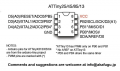
Looking at it, it seems doable but no idea when you see a pin out like 1660328980812.png
and no example circuits to demonstrate what is required in terms of components.

Got any examples I can look at? There doesn't appear to be enough pins to button press, selector, LED's.
 
Top