Build a circuit that is a variable timer(NE555P) in seconds It has a start state with two LED's.

djsfantasi

Joined Apr 11, 2010
9,237
Looking at it, it seems doable but no idea when you see a pin out like View attachment 273706
and no example circuits to demonstrate what is required in terms of components.

Got any examples I can look at? There doesn't appear to be enough pins to button press, selector, LED's.
Simply, ignoring the confusing pin labels for now…

You need two input pins.
  • Time select (an analog input)
  • Push button
You need two output pins.
  • Green LED
  • Red LED
That’s a total of four pins. You have 6 pins available (8 pins less 2 power pins).

Looks like it will work for you.
 

WBahn

Joined Mar 31, 2012
33,040
Circuit #2 or 3 would be good option for near to 10 seconds.
I didn't make myself sufficiently clear.

Instead of calling them Circuit #n, let me rephrase it this way.

You give Bob, Sue, and Tim each one of your devices in order to play the game. Bob's device times out in 9.5 s, while Sue's device times out in 10 s and Tim's device times out in 10.5 s.

Later, you give a different set of devices to Amy, Joe, and Kim to play another round of the game. Amy's device times out in 8.4 s, Joe's device times out in 8.5 s, and Kim's device times out in 8.6 s.

The question is which set of players, all else being equal, are more likely to enjoy the game and not be frustrated because the timers weren't all exactly 10 s? The first group, whose timers were closer to the 10 s target, or the second group, whose timers were all much closer to matching each other.

Your subsequent answers make it seem like it shouldn't matter and that the kids won't notice the differences in either case.
 

WBahn

Joined Mar 31, 2012
33,040
I know that you have said that you played with Arduinos before and didn't want to go that route. If so, that's fine and we can continue down a 555 or other non-MCU path.

But do consider the potential benefits of using one of the small, low-cost MCUs that are out there. If you use an 8-pin part that has six I/O pins, you can use two outputs for the two LEDs, one input for the push button, and the other three inputs for simple switches to control the time setting, which would give you eight different time options. This would be relying on the part's internal oscillator for the timing, which should be good enough given your description of the application's needs. This would give you an extremely small and simple circuit to work with compared to what you are looking at using multiple 555 timers and all of the associated circuitry. Also, you would have a lot of flexibility in changing how you want the devices to behave. Want to have one or both LEDs flash? Change the program to make them flash.

If you have any interest in doing other electronics projects at all, the up-front cost in getting a programmer and learning how to write programs will be well worth it.
 
Last edited:

eetech00

Joined Jun 8, 2013
4,716
Looking at having a selector switch to set a range of times like 5, 10, 20 ,30 seconds.
Here is my first pass at a design:

As discussed earlier, the red LED will initially be OFF and begin to Flash when the start button is pressed to indicate the timer is running. When the time expires, the red LED will go dark and the green LED will light steady. When the reset button is pressed, the green LED will go dark, and the circuit is ready for another cycle.
The circuit uses three IC's, 1-74HC132 NAND, and 2-NE555's.
Too bad you already have NE555's, the CMOS version of the timer (LMC555) would take much less power.
I've shown standard LED's operated at a lower current (10mA) but if you use high efficiency LED's, they can operated at a lower voltage and current, and still remain bright.

1660336669931.png

1660336731250.png
 

crutschow

Joined Mar 14, 2008
38,621
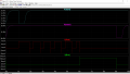
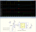
Here's the LTspice simulation of a relatively simple circuit (as simple as I could think of) using one 555 timer and a NC (Normally Closed) push-button, that does, as I understand, what you requested in your first post.
It does not blink the LEDs but just turns them on and off.

If circuit power is applied and the NC push-button (yellow trace) is not pressed (0V), then the red LED (red trace) is on and the green LED (green trace) is off (since the TRIG voltage is low, and thus the OUT is high).
When the PB is pressed (goes open) the red LED goes out and the timer capacitor starts charging (blue trace).
If the PB is released before the time-out (shown at 20s), then the timer is reset and the red LED again illuminates.
If the PB is pressed for longer, then the 555 will time out (OUT goes low) when the blue trace reaches 2/3 of the supply voltage (here at about 52 seconds), turning on the green LED.
Releasing the PB after the green LED goes on also resets the circuit as shown at 70 seconds.

The time-out is close to 1.1 * R2C1 time-constant, with the values shown giving a simulated time of about 22 seconds between the press of the PB and the green LED lighting.
You can switch in different values of R2 if you want switchable time-out times.
You can us pots for the resistors, if you want to be able to tweak each unit to the same timeout.

1660402210549.png
 
Last edited:

Thread Starter

damnucircuit

Joined Aug 12, 2022
20
I didn't make myself sufficiently clear.

Instead of calling them Circuit #n, let me rephrase it this way.

You give Bob, Sue, and Tim each one of your devices in order to play the game. Bob's device times out in 9.5 s, while Sue's device times out in 10 s and Tim's device times out in 10.5 s.

Later, you give a different set of devices to Amy, Joe, and Kim to play another round of the game. Amy's device times out in 8.4 s, Joe's device times out in 8.5 s, and Kim's device times out in 8.6 s.

The question is which set of players, all else being equal, are more likely to enjoy the game and not be frustrated because the timers weren't all exactly 10 s? The first group, whose timers were closer to the 10 s target, or the second group, whose timers were all much closer to matching each other.

Your subsequent answers make it seem like it shouldn't matter and that the kids won't notice the differences in either case.
It wouldn't matter because the game site is a fast paced game site that I plan on using and no one would perceive such a difference in time. I would be looking at as close to the desired times as possible but its not essential.

I know that the555's can be set by use of resistors to give nearest timings. if this was absolute timings than I would employ someone to make these things for me to exacting specifications, however I am not, near enough is good enough.
 
You are trying to run a marathon without having learned to crawl or walk. You need to work up to your goal by starting to understand the simpler pieces of a complex circuit.
Quite right Papabravo! If we had not started life as "small" we would not be here... ( you must be showing your age?)HI.
 

Papabravo

Joined Feb 24, 2006
22,098
Quite right Papabravo! If we had not started life as "small" we would not be here... ( you must be showing your age?)HI.
I'm not sure my age is necessarily showing, but perhaps my experience of watching others approach a complex subject without adequate background or preparation. It is as if they expect the availability of "shortcuts" that will allow them to achieve a goal without the expenditure of effort. I started my journey by learning the FORTRAN programming language. Now here I am designing and simulating analog circuits. This did NOT happen overnight.
 

Thread Starter

damnucircuit

Joined Aug 12, 2022
20
Here's the LTspice simulation of a relatively simple circuit (as simple as I could think of) using one 555 timer and a NC (Normally Closed) push-button, that does, as I understand, what you requested in your first post.
It does not blink the LEDs but just turns them on and off.

If circuit power is applied and the NC push-button (yellow trace) is not pressed (0V), then the red LED (red trace) is on and the green LED (green trace) is off (since the TRIG voltage is low, and thus the OUT is high).
When the PB is pressed (goes open) the red LED goes out and the timer capacitor starts charging (blue trace).
If the PB is released before the time-out (shown at 20s), then the timer is reset and the red LED again illuminates.
If the PB is pressed for longer, then the 555 will time out (OUT goes low) when the blue trace reaches 2/3 of the supply voltage (here at about 52 seconds), turning on the green LED.
Releasing the PB after the green LED goes on also resets the circuit as shown at 70 seconds.

The time-out is close to 1.1 * R2C1 time-constant, with the values shown giving a simulated time of about 22 seconds between the press of the PB and the green LED lighting.
You can switch in different values of R2 if you want switchable time-out times.
You can us pots for the resistors, if you want to be able to tweak each unit to the same timeout.

View attachment 273739
@crutschow D2 - can this be a general purpose diode like a 1N4001 of which I have about 100 of them?
 
Last edited by a moderator:

crutschow

Joined Mar 14, 2008
38,621
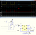
can this be a general purpose diode like a 1N4001 of which I have about 100 of them?
It can.
It will just slightly raise the capacitor discharged voltage which will give a slightly shorter time-out.
(My simulated time-out was reduced to 20 seconds from over 21 seconds with the Schottky diode)
Should not be a problem in your application.

Alternately you could use a small NPN transistor (e.g. 2N3904, 2N2222, etc.) instead of the diode, which would not have that diode drop for the capacitor discharged voltage.
This circuit would also have less change in timing with temperature, but that's not enough to be of concern in your application.
The simulation below now shows a time-out of 21.9s, close to the theoretical calculated value of 1.1 * R2C1:

Note that the calculated time is affected by the tolerance of the R2 and C1 values.
1% resistors are common, but electrolytic capacitor will have a much higher tolerance, with 20% being typical.
For one timing period, you could just adjust the value of R2 to compensate.
If you have several selectable timing resistors. then the added 25kΩ trimpot U1 (below) will allow adjustment of all the time periods to compensate for this large capacitor tolerance, by adjusting the THRS trigger voltage.
Then the main timing inaccuracy for the other timing resistors would be due to the timing resistor tolerances.
A pot wiper setting at the 50% point gives the 1.1 * R3C1 time-out.
If that capacitor timing variation is not important, then you can eliminate pot U1 and R5, and leave pin CV open.

1660527140799.png
 
Last edited:

Thread Starter

damnucircuit

Joined Aug 12, 2022
20
Sorry, I'm out the game for a couple of weeks, being treated for Lymes Disease so I'm not up to doing anything when the antibiotics have done their job I shall be back to try some of the suggestions.

In the meantime, thanks to all who made suggestions.
 
Top