 Facebook
 Google
 GitHub
 Linkedin
Greeting everyone,
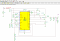
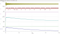
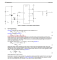
iam trying to use conventional buck converter (lm5117) as constant current source for variable resistive load (8-14 ohms). I managed to simulate constant voltage, but resistance of load can almost double so my current drops a lot. When I tried typical application scheme from datasheet (https://www.ti.com/lit/ds/symlink/l...l=https%3A%2F%2Fwww.ti.com%2Fproduct%2FLM5117) figure 35 analysis shows that nothing happens. It is very probable that i made novice mistake somewhere.
Attached:
Image 1 - Scheme
Image 2 - Transient analysis
Thanks in advance for any useful answers.
Mike
Attachments
-
 56.9 KB Views: 37
 -
 38.5 KB Views: 34
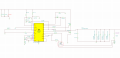
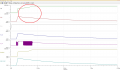
") But that divider only reduces voltage and does not change rising tendency of voltage, it would also rise if divided only it would be smaller value, my problem is that CM is rising while voltage across R_sense is gettig lower. I am working on stability, set up wanted current should be quide easy afterwards.
But that divider only reduces voltage and does not change rising tendency of voltage, it would also rise if divided only it would be smaller value, my problem is that CM is rising while voltage across R_sense is gettig lower. I am working on stability, set up wanted current should be quide easy afterwards.


