Breadboard Compatible Relay

SamR

Joined Mar 19, 2019
5,488
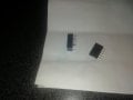
Sorry for the short answers, I was out of town and using my phone. Signal Relays AKA 10 pin relays are usually actually 8 pins, 2 coil, 6 DPDT. The other 2 pins are for the Latch on latching relays only and not as common. Typically 3, 5, 6, 9, 12, 24, 48 VDC coils w/ 5A or less rated contacts up to 250VAC/220VDC or less. Designed to conform to DIP mounting standards and typically have small pins that do not fit breadboards very well (now some surface mount)IMG_0586[1].JPG. In fact, they are downright aggravating. So I built a protoboard module using a 16 pin DIP socket with 2 rows of female headers on each side. So that each DIP socket pin is connected to 2 header sockets. The small relay pins fit snuggly into the DIP socket and the female headers fit the jumper wires snuggly giving a good solid connection that you cannot get with a breadboard.IMG_0583.JPGIMG_0584.JPG
 

Thread Starter

RAMBO999

Joined Feb 26, 2018
259
Back again. On the subject of breadboard pin headers.

Yes. Good advise because this relay has demonstrated a tendency to spontaneously leap off the board like a Mexican jumping bean. Which is a nuisance.

So I bought some female pin headers like the ones you see in the attached pic. That's the relay on the left. It has very thin pins.

The 5 pin item on the right is the pin header. Cut from a larger piece of course.

These headers are neither use nor ornament because a) the pins are no longer than those on the relay and b) the small sockets are too deep for the pins on the relay. Pins on the relay and the header are both 3 mm x 0.33 mm x 0.55 mm.

All in all, these headers are no use for this particular application.

Can anyone suggest a suitable header for this relay? I have had a good look around but nothing seems suitable.

Thanks
 

Attachments

Last edited:

dl324

Joined Mar 30, 2015
18,327
Can anyone suggest a suitable header for this relay? I have had a good look around but nothing seems suitable.
If you're not getting a good connection in a breadboard, it's unlikely that you'll get a good connection in a female header designed for 0.025" square pins.

Have you tried a machined pin socket?

Or considered something like this:
clipimage.jpg
Machined pin wirewrap strip.
 

Thread Starter

RAMBO999

Joined Feb 26, 2018
259
If you're not getting a good connection in a breadboard, it's unlikely that you'll get a good connection in a female header designed for 0.025" square pins.

Have you tried a machined pin socket?

Or considered something like this:
View attachment 197333
Machined pin wirewrap strip.
I was looking at something similar an hour ago. They have shorter sockets. But one other problem with the ones I bought is the small clip inside the socket. They are flat and layed out parallel to the pins on the relay so they don't engage at all. Here's the vid I watched. I am talking about the white pin headers that the guy has in his hand in the first few seconds. Do you know these headers. Will the sockets grab a 3 mm x 0.33 mm x 0.55 mm pin on the relay?


dl324

Joined Mar 30, 2015
18,327
Will the sockets grab a 3 mm x 0.33 mm x 0.55 mm pin on the relay?
The strip I showed uses typical machined pin socket dimensions. They should hold DIP pins that are 0.38-0.53mm wide.

I find that standard machined pin sockets (DIP and SIP) make good contact in a solderless breadboard.

The female header you tried seems to be of this type:
clipimage.jpg
You'd be unlikely to get a good connection with a pin that wasn't 0.025" square.
 

SamR

Joined Mar 19, 2019
5,488
Which is exactly why I made the relay/chip socket module shown above. Brand New breadboards sorta work but after sticking big stuff into sockets they tend to stretch out a bit and make using a relay on the board a pain in the a**. I like to use 1/2W resistors instead of 1/4W and 1W leads are too large and make breadboard sockets sloppy in a hurry. Building the relay socket module didn't take much effort (if you have the parts) and was time well spent for me compared to the hassle of trying to hold the relay down with a finger and pushing it about to make good contact. Yes, signal relays are designed for DIP mounting and fit breadboard but not very well on a used board.
 

Thread Starter

RAMBO999

Joined Feb 26, 2018
259
The strip I showed uses typical machined pin socket dimensions. They should hold DIP pins that are 0.38-0.53mm wide.

I find that standard machined pin sockets (DIP and SIP) make good contact in a solderless breadboard.

The female header you tried seems to be of this type:
View attachment 197336
You'd be unlikely to get a good connection with a pin that wasn't 0.025" square.
Yes. That is what I have. Not really that good to be fair. As Sam points out he has clearly had a similar experience and went his own custom way. I will give that some thought.
 

SamR

Joined Mar 19, 2019
5,488
I used a 16 pin DIP socket and still have room to add a 28 pin socket if I want to. DIP chips can also be a bear on stretched out breadboards so the module is handy.
 

Thread Starter

RAMBO999

Joined Feb 26, 2018
259
I used a 16 pin DIP socket and still have room to add a 28 pin socket if I want to. DIP chips can also be a bear on stretched out breadboards so the module is handy.
Just looking at them. I can see that the pins would fit into the breadboard but will the sockets up top actually grip these miniscule pins on my relays without having to wiggle them about? That's the issue really. Their looseness. The female headers were muy second purchase. I actually bought male headers first thinking they were hollow.
 

MaxHeadRoom

Joined Jul 18, 2013
30,660
DIP 300 relays have been mentioned, I have used the DPST types for breadboard/Vero board before.
Also fits a standard DIP socket.
Max.
 

SamR

Joined Mar 19, 2019
5,488
Yep the pins fit tightly into socket. You could use a ZIF socket but they cost more and standard socket works fine. Never used the DIP chip relays, are they solid-state? Might have to look into that.
 

Thread Starter

RAMBO999

Joined Feb 26, 2018
259
Yep the pins fit tightly into socket.
Cheers. I will order some. As for the solid stateness, maybe. They are small and don't really do anything that you couldn't achieve using a transistor but they do contain a "coil" which suggests thet the technology may be even more simple than that. Also the fact that there is an audible click when energised tends to suggest that they are electro mechanical in nature.
 
Last edited:
Top