Bootstrap capacitor in power amplifier....

Thread Starter

Himanshoo

Joined Apr 3, 2015
265
Hi guys ....

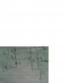
In order to get a rail to rail output "Bootstrap capacitor" are used...

Is the 'bootstrapping concept' is to make the output voltage independent of R4 or the voltage across R4....????

The minimum voltage drop across R4 limits the output voltage rail to rail swing capability thus decrease amplifier efficiency...so R4 is divided into two parts ..across the lower resistor Ry a bootstrap capacitor is connected ...which do not let the voltage vary across Ry..whatever the opamp output is...ok

Now according to circuit analysis equation 1 tells that if R4 increases or VR4 increases ..then IL will decrease which will further decrease Vout..

Is the real requirement is to increase the voltage drop across Ry or to make R4 vanish(independent of Vout) from the equation 1...to make Vout to swing to rail limits..


Vcc = VR4 + Vbe + Vo = IR4 * R4 + Vbe + IL* RL ..

Also IR4 = IL/(β + 1).
IL = (Vcc - Vbe)/( RL + R4/(β + 1)) ----------------------------1
and
Vo_max = IL * RL (peak value)


please help....
 

Attachments

crutschow

Joined Mar 14, 2008
34,470
The purpose of the bootstrap capacitor is to allow the voltage of R4 to rise above Vcc and still supply current to the base of the transistor when the emitter voltage rises close to the supply voltage, i.e the voltage across R4 does not vary significantly with the signal voltage.
 

Jony130

Joined Feb 17, 2009
5,488
Without input signal DC voltage in the circuit looks like this

1.PNG

And notice that C1 capacitor is charged to a potential difference of 7.85V. And the time constant is very long (t = Rx||Ry * C1 = 0.544s) compared to the audio signal period (1/20Hz = 0.05s). And from this we can tell that the capacitor will act just like a 7.85V DC voltage source.
http://forum.allaboutcircuits.com/threads/voltage-divider-bias.71104/#post-494950
And this is the key to understand how this circuit work.

Let as assume that voltage at the output is 10V, so we have this situation:

2.PNG

As you can see the voltage at Vx node can be even higher than Vcc. And this is why +Vo_max is now equal Vcc - Q1Vce(sat) ≈ 14.8V.
But do not forget that this is true only ifopamp is able to provide a current larger than 2Vcc/R4
 
Last edited:

Thread Starter

Himanshoo

Joined Apr 3, 2015
265
Without input signal DC voltage in the circuit looks like this

View attachment 89956

And notice that C1 capacitor is charged to a potential difference of 7.85V. And the time constant is very long (t = Rx||Ry * C1 = 0.544s) compared to the audio signal period (1/20Hz = 0.05s). And from this we can tell that the capacitor will act just like a 7.85V DC voltage source.
http://forum.allaboutcircuits.com/threads/voltage-divider-bias.71104/#post-494950
And this is the key to understand how this circuit work.

Let as assume that voltage at the output is 10V, so we have this situation:

View attachment 89958

As you can see the voltage at Vx node can be even higher than Vcc. And this is why +Vo_max is now equal Vcc - Q1Vce(sat) ≈ 14.8V.
But do not forget that this is true only ifopamp is able to provide a current larger than 2Vcc/R4
Ok the key here is to drive the transistor into saturation ….and for that we need a voltage of Vcc+Vbe (as it is a emitter follower) at the base of Q1 ..which is only possible if there is a high voltage at node Vx ..at least higher than Vcc..and the role of bootstrap capacitor here is to raise the voltage at Vx above the supply voltage..

Am I right….?


Suppose just for curiosity if Ry is replaced by a potentiometer and voltage drop across Ry is made to vary …then what impact it will make on the circuit…??
 

ian field

Joined Oct 27, 2012
6,536
The purpose of the bootstrap capacitor is to allow the voltage of R4 to rise above Vcc and still supply current to the base of the transistor when the emitter voltage rises close to the supply voltage, i.e the voltage across R4 does not vary significantly with the signal voltage.
I always thought it was more to do with linearity.

The simpler types of MOSFET high side switch simply won't work without a bootstrap capacitor to generate Vgs at least 6V above Vdd.

The 0.7V Vb/e of a transistor isn't at such a disadvantage, but as the base voltage rises the current through the bias resistor falls.

Bootstrapping also acts as regeneration that increases the gain of the output stage, and also its input impedance.
 

AnalogKid

Joined Aug 1, 2013
11,056
A higher quality amplifier circuit would replace Rx and Ry (post #3) with a true constant current source to improve both linearity/distortion and peak output power capability. One way to characterize the bootstrap circuit is that it creates a constant current source without additional semiconductors. Anytime there is a constant voltage across a resistor there is a constant current through it. As shown, when the output goes from 0 V to 10 V, the voltage across Ry remains 7.15 V. Thus the current through Ry is constant, and its effective resistance is infinite. With an opamp driver stage, the improvement is more in the headroom area and less in the distortion area. As shown in another thread with a typical common emitter voltage amplifier instead of an opamp, the linearity improvement is dramatic.

ak
 

Jony130

Joined Feb 17, 2009
5,488
Ok the key here is to drive the transistor into saturation ….and for that we need a voltage of Vcc+Vbe (as it is a emitter follower) at the base of Q1 ..which is only possible if there is a high voltage at node Vx ..at least higher than Vcc..and the role of bootstrap capacitor here is to raise the voltage at Vx above the supply voltage..
Am I right….?
Yes you're right
Suppose just for curiosity if Ry is replaced by a potentiometer and voltage drop across Ry is made to vary …then what impact it will make on the circuit…??
Well for example If you lower Ry value the quiescent current will increase and Vx voltage will drop.
I always thought it was more to do with linearity.
Not in this case, with this type of a "driver" for a push-pull output stage the bootstrap capacitor increase the positive output voltage swing.
 

ian field

Joined Oct 27, 2012
6,536
Yes you're right

Well for example If you lower Ry value the quiescent current will increase and Vx voltage will drop.

Not in this case, with this type of a "driver" for a push-pull output stage the bootstrap capacitor increase the positive output voltage swing.
...............which avoids the non-linearity that would occur since the base bias resistor passes less current due to the voltage across it decreasing.
 
Top