Blower Motor Speed Controller

Thread Starter

Dale1700

Joined Mar 15, 2019
15
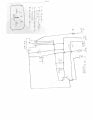
I've been unsuccessful in finding a wiring schematic for a blower motor speed controller controlled by an Electronic Automatic Temperature Control ( EATC) module in automobiles in order to test the various components. So I've taken one apart and thought I'd try drawing one myself. Attached is my start at identifying the component parts. I'm wondering if anyone can identify the large black component with the question mark on the upper right of the pix, and the totally black C-? component that looks like a ceramic capacitor ( but it has no markings). I'd also like to know what is the type of signal that comes from the EATC module that drives the blower motor control module....variable dc ??


Blower  Motor Controller.JPGBlower  Motor Controller.JPG
 

geekoftheweek

Joined Oct 6, 2013
1,201
I second Max, but without the PCT part... a relay of some variety for sure. It is not unusual for blower motors to run off of some form of PWM signal. Sometimes the frequency is changed to indicate desired speed, other times the frequency stays the same and the duty cycle is what determines speed. It could also be variable voltage, although in my mind it looks too simple of a design for that.
 

Thread Starter

Dale1700

Joined Mar 15, 2019
15
The top item is a sealed PCT relay.
The lower black item looks like a C or a MOV, does any of them have markings?.
Max.
Thanks Max, Knowing the components as a PCT and possibly an MOV is very helpful. Unfortunately the lower black item has no markings at all. But tracing the printed contacts on the printed circuit board may give a clearer idea of what it is. The circuitry wiring should be fairly simple since the plated side of the circuit board doesn't look that complicated in tracing the components connections.Blower Motor  Control Pix 99Linc 3 of 3 100_2098.JPG
 

MaxHeadRoom

Joined Jul 18, 2013
28,619
Out of interest, measure the resistance between the bottom most two pins shown on the foils side, bottom left,there is 3 & 2 vertically.
A small one and the larger one.
Max.
 

geekoftheweek

Joined Oct 6, 2013
1,201
To me the top large pin looks to be a ground. The bottom large pin would be the - from your motor. The top small pin I don't know. The middle small pin would be your transistor base pin. The bottom small pin would be your relay control.

The relay gets turned on for high speed fan while the transistor handles the variable speed portion.

A couple guesses...
R2 maybe part of a different circuit altogether placed here for convenience.
D1 flyback diode for relay.
 

Thread Starter

Dale1700

Joined Mar 15, 2019
15
To me the top large pin looks to be a ground. The bottom large pin would be the - from your motor. The top small pin I don't know. The middle small pin would be your transistor base pin. The bottom small pin would be your relay control.

The relay gets turned on for high speed fan while the transistor handles the variable speed portion.

A couple guesses...
R2 maybe part of a different circuit altogether placed here for convenience.
D1 flyback diode for relay.
---------------------------------------------------------------------------------------------------------
Here's info I found on the power resistor which gives a good idea of how it biased, along with the emitter, base and collector of it. Glad the controller uses discrete components. This engineer trained on vacuum tubes and 3 lead single transistors in a can ! 1595020153853.png
 

Thread Starter

Dale1700

Joined Mar 15, 2019
15
Here's the progress so far. I'm trying to see if I can find if the PTC actually has five pin connections ( it a bit iffy due hard to determine without taking it off the PCB) and it's specific wiring. There is one very small capacitor marked C that can't be determined without taking it off of the PCB....and then if may not have markings.

Thanks for your help.


Blower Motor Cont. Wiring Diag..JPG
 

Attachments

Alec_t

Joined Sep 17, 2013
14,280
The black 'C' component looks to be connected directly between collector and emitter of the transistor so presumably is a TVS.
 

Thread Starter

Dale1700

Joined Mar 15, 2019
15
Max, In response to your question:
" Out of interest, measure the resistance between the bottom most two pins shown on the foils side, bottom left,there is 3 & 2 vertically. A small one and the larger one. "
Answer 100 ohms . If my wiring diagram is correct the pins you mentioned are #1 going through the diode and relay to the #4 pin ( gnd). I measured the 100 ohms with a Extech MA250 digital meter, reversing the meter leads gave the same 100ohm. . To check, I used an old analog Simpson 260 with the same results ( 100 ohm) using the X100 scale.

If I identified the diode component correctly, I would have expected a fairly large difference in resistance when reversing the meters leads. I can't explain why a diode would be necessary in the relay circuit which evidently is only used at high speed when the dash's variable speed motor control is not operating properly.

I'm trying to get some info on the wiring and pinout of the relay so I can complete my attempt at a wiring diagram.
 

MaxHeadRoom

Joined Jul 18, 2013
28,619
You cannot measure a diode with the resistance leads, you need a source that will provide the forward current, such as the Diode/continuity test range that is a feature of most meters.
The 100Ω measurement was as I suspected, the probability that it was the relay coil resistance.
The diode may be the reverse emf diode across the coil.
Max.
 

Thread Starter

Dale1700

Joined Mar 15, 2019
15
Max, I'm a bit puzzled about your statement " You cannot measure a diode with resistance leads...." Perhaps I'm misunderstanding something. Here' the general 'thumb rule ' I've used in the past which generally proved pretty reliable in testing diode ( and other semiconductors with diode junctions) as 'good' or 'bad'.

In the low resistance measuring range the Simpson 260 supplies 1 1/2 vdc to the diode through its leads to forward and reverse bias the diode. In forward bias the diode conducts, has a voltage drop about 5. to .8 volts across it, and a resistance is measured..usually less than a hundred ohms or so..... depending on the diode. When reversed biased, the diode will not conduct ( if its good) and the resistance measured will very high.

One has to be careful in the voltage used to test diodes this way. Too high a voltage will blow out any diode junction when forward biased.
 

MaxHeadRoom

Joined Jul 18, 2013
28,619
Most meters, Fluke etc, used to test a diode with a VOM on the resistance range are not able to supply the current to forward bias it, hence the reason for the Diode test range, this range provides the neccesary current and actually measure the volt drop across the diode when testing.
Of course the Simpson I remember is the older analogue meter so the conditions are different.
Max.
 
Last edited:
Top