 Facebook
 Google
 GitHub
 Linkedin
I'm trying to design an ESC for a drone project. This ESC has 4 independent ESC's, each driving an individual motor. The design should be rated so each ESC can use 30A. I've based the design to be compatible with the SimonK firmware, so the processor is a ATMega8 (https://github.com/sim-/tgy). I've attached PDF, EAGLE .brd and .sch files below. Btw, there a gimbal controller on board as well (not part of this problem, and not being used yet).
When I test the motors without load (no propeller), they throttle all the way up and down with no problems (consuming about 4A total). However, when I attach the propellers, the ESC's only get to about 1/3 max throttle, and just shut off (I believe they are resetting for some reason). To make things worse, the last motor test I did blew up my voltage regulator. It was a triple switching buck converter on board that converts the 11-17V of the battery to 1V8/3V3/5V for the Raspberry Pi, STM32's and ATMega8's.
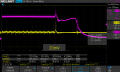
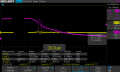
Luckily, during this last test, I was suspecting that a brownout or something was happening on the 5V rail, resetting the ATMega's, so I was probing it with my scope, along with one of the motor input PWM signals. I managed to capture the dying breath of the regulator, but I am still unsure exactly the cause of death. From the 5V rail (CH2 from the scope), it looks like there was a massive positive, and negative spike followed by complete loss of power (suggests an EMI problem? Not enough bulk capacitance?). There is about 1500uF of bulk capacitance on the board. I also measured the noise of both the 5V rail and the PWM signal, and both are from the 18kHz motor switching frequency. I've attached the pictures from the scope (sorry that some of the images are clipped, not sure why that happened, and when I measured the spike, I now realize I was on CH1 measure instead of CH2 *facepalm*).
When I test the motors without load (no propeller), they throttle all the way up and down with no problems (consuming about 4A total). However, when I attach the propellers, the ESC's only get to about 1/3 max throttle, and just shut off (I believe they are resetting for some reason). To make things worse, the last motor test I did blew up my voltage regulator. It was a triple switching buck converter on board that converts the 11-17V of the battery to 1V8/3V3/5V for the Raspberry Pi, STM32's and ATMega8's.
Luckily, during this last test, I was suspecting that a brownout or something was happening on the 5V rail, resetting the ATMega's, so I was probing it with my scope, along with one of the motor input PWM signals. I managed to capture the dying breath of the regulator, but I am still unsure exactly the cause of death. From the 5V rail (CH2 from the scope), it looks like there was a massive positive, and negative spike followed by complete loss of power (suggests an EMI problem? Not enough bulk capacitance?). There is about 1500uF of bulk capacitance on the board. I also measured the noise of both the 5V rail and the PWM signal, and both are from the 18kHz motor switching frequency. I've attached the pictures from the scope (sorry that some of the images are clipped, not sure why that happened, and when I measured the spike, I now realize I was on CH1 measure instead of CH2 *facepalm*).
Attachments
-
 37.4 KB Views: 8
 -
 27 KB Views: 6
 -
 35 KB Views: 6
 -
 32.4 KB Views: 6
 -
 29.2 KB Views: 6
 -
 33.4 KB Views: 6
 -
 40.7 KB Views: 6
 -
160.1 KB Views: 7
-
384.3 KB Views: 3


