BLDC Controller - Electrical noise reduction ideas

Thread Starter

JJM101

Joined Jul 27, 2014
15
Hello,

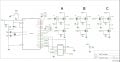
I am working on a BLDC controller and I want to get some ideas for what to do to reduce the noise in the circuit as much as possible. I currently have this circuit on a PCB. It is a high power circuit >1000W, and whenever I go to run the motor, it starts to run, but the noise in the system eventually disrupts the microcontroller and it stops working.

Attached is the schematic of my project. It is a fairly simple circuit...Hall sensors on digital pins, an AND gate chip that allows me to use only one PWM pin, 6 digital pins to commutate the motor, *there are 2 FETs in parallel, so 12 total (not shown in my schematic)

I want to try to get this board running as well as possible before ordering another PCB. (it is part of another PCB that will be expensive).
 

Attachments

MaxHeadRoom

Joined Jul 18, 2013
28,684
For a 20amp possible load, you will need a fairly large capacitor on the 48vdc supply, also I would ensure decoupling capacitors strategically placed.
The fact that both supplies commons are connected the ground plane, the motor plane should be kept completely away from the logic side.
Another electrolytic on the board itself at the motor terminals would be advisable, especially if the main caps are in a separate supply.
Max.
 

Thread Starter

JJM101

Joined Jul 27, 2014
15
I will add a larger cap at the power in from the 48V supply. 1000uF?

The decoupling caps...should i just add a 0.1uF to my 'power in' to the uC? and just make sure they are close as possible?

The capacitors at the motor terminals...would it be from the motor terminal to ground? Or from power in to ground?

*The board will receive power from batteries. I am testing on a switcher now though.

Thanks for the help... I haven't had much experience with eliminating so much noise.
 

3ldon

Joined Jan 9, 2010
82
your incredibly high resistor values are almost certainly causing shot through currents when both fets are on at the same time.

use a proper gate driver such as an ir2111 or something similar.

additionally you need a few thousand micro farads from 48v to ground, and the loop area formed by the 6 switches and the the capacitor(s) need to be as small as possible to reduce the inductance to reasonable values.
 

Thread Starter

JJM101

Joined Jul 27, 2014
15
your incredibly high resistor values are almost certainly causing shot through currents when both fets are on at the same time.

use a proper gate driver such as an ir2111 or something similar.

additionally you need a few thousand micro farads from 48v to ground, and the loop area formed by the 6 switches and the the capacitor(s) need to be as small as possible to reduce the inductance to reasonable values.
I'm going to add some caps to the 48v input and reduce any inductance between the different switch configurations.

The gate driver... I thought a gate driver was used to allow you to use an N-Channel as a high side switch. Could you explain its application in my case?
Also could you explain the "shot through currents"? i haven't heard of that before

Thanks for the help
 

PeterCoxSmith

Joined Feb 23, 2015
148
"The gate driver... I thought a gate driver was used to allow you to use an N-Channel as a high side switch. Could you explain its application in my case? Also could you explain the "shot through currents"? i haven't heard of that before"

Gate drivers are essential to to a motor bridge. They are push/pull devices that turn the mosefet gates on and off with plenty of current which they need for a short pulse. High value resistors make the mosfets switch slow and with unmatched turn on/off times.

Shoot through occurs when for example a low side mosfet is turning off too slow when a high side mosfet turns on fast and you get both on momentarily in which case there is a short circuit or shoot through from the motor supply + to ground.
 

Thread Starter

JJM101

Joined Jul 27, 2014
15
Thanks for the help guys. The link was also very helpful. I will go in the direction of using the gate driver. The PCB is definitely scrap.

So from what I have gathered from you guys about the noise getting to the microcontroller...
- more decoupling caps at power in to the microcontroller
- bigger cap or two at 48V power in
- isolate ground plane from microcontroller
- gate drivers to switch the FETs better and prevent the shot through current
 
Top