BJT transistor selection

Thread Starter

birdtrick

Joined Dec 1, 2016
21
Hi,

Disclaimer.. very new to electronics.

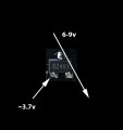
I need to replace a BJT transistor (well I'm pretty certain that is what it is) on a PCB and am unfamiliar with how to make the right selection. I tried to simply find the exact replacement through the marking on the device, but had no luck. The marking is 024V1 if anybody has an idea..

The transistor switches on a 6-9v DC circuit when an approximate 3.7v signal is applied. The current is only 2 amps or so. I am just wondering if there are any voltage or current specifications I need to be aware of in selecting the best replacement.

I've attached a photo of the component.

Thanks,

Troy
 

Attachments

MrAl

Joined Jun 17, 2014
11,474
Hi,

2 amps is a lot for a small thing like that.
If it really is 2 amps then it might be a low sat transistor. These have a very low Vsat rating.

Do you know if it is NPN or PNP?

Do you know what kind of circuit it is switching or if it is a linear circuit?
 

#12

Joined Nov 30, 2010
18,224
Sounds like an n-channel mosfet to me. No bipolar transistor can switch 2 amps in that small of a package without overheating.
I can't find a sot23-3 with a low enough Rds.:( That 2 amp number is crashing the party.
 

Thread Starter

birdtrick

Joined Dec 1, 2016
21
Thanks for the replies. This is why I'm here. So maybe it's not a bipolar transistor after all. I am going to look into the amps more and will reply what I find out. I might have that entirely wrong.
 

hobbyist

Joined Aug 10, 2008
892
I found this earlier on the internet, would this be the device?

The transistor 024V1 is a discrete electronic device that performs a single transistor function and is composed of many elements being structurally an integrated circuit, for example, a compound transistor or a lot of high power transistors. Transistors are divided into two classes that are different in structure, operating principle and parameters, i.e. bipolar and field-effect (monopolar) ones.
 

MrAl

Joined Jun 17, 2014
11,474
Sounds like an n-channel mosfet to me. No bipolar transistor can switch 2 amps in that small of a package without overheating.
I can't find a sot23-3 with a low enough Rds.:( That 2 amp number is crashing the party.
Hi,

Not sure why you would say something like that. Zetex made transistors that can do 6 amps.
The key is to have low Vsat and fast switching times. That equates to low power loss at higher amps.
That's why i mentioned low Vsat in my previous post. A Vsat of 100mv and 2 amps is less than a quarter watt, and we may find them as low as 50mv.
Over the last 10 or 20 years things have really changed in bipolars as well as other transistor types.

Is it really a bipolar though? We can not know that for sure unless we have more data or measurements, but since it is broken we cant measure so we have to guess. Can it be Mosfet? Why not, but just for the 2 amp spec alone we can definitely not rule out bipolars.

Zetex is now Diodes Inc., but back when used their stuff they were just Zetex.

To everyone reading:
The number does seem to correlate to one of the posts in this thread so maybe that's it.
Also, if we had a schematic of more of the circuit we could also specify a transistor that would work wen without knowing the original part number. So if all else fails, that would help.
 

Thread Starter

birdtrick

Joined Dec 1, 2016
21
I found this earlier on the internet, would this be the device?

The transistor 024V1 is a discrete electronic device that performs a single transistor function and is composed of many elements being structurally an integrated circuit, for example, a compound transistor or a lot of high power transistors. Transistors are divided into two classes that are different in structure, operating principle and parameters, i.e. bipolar and field-effect (monopolar) ones.
Well that certainly seems like exactly the device. Where in the heck did you find that? I've been searching everywhere and found nothing close.

I believe I am actually working with .2 amps, not 2. Looking at the attached picture, when I switched between the 10A range and the two on either side of it, the decimal point simply moved one position each way. It led me to believe I needed to multiply the reading by 10A..
 

Attachments

PeteHL

Joined Dec 17, 2014
475
@birdtrick. In taking readings in other than the 10A range, did you insert the red (positive) lead into the jack on the right-hand side of the meter? Of course if your current is greater or equal to 200 mA, you must use the 10A range or you will blow a fuse in the meter.
 

hobbyist

Joined Aug 10, 2008
892
Well that certainly seems like exactly the device. Where in the heck did you find that? I've been searching everywhere and found nothing close.
I googled "024v1 transistor", and this was on the list of websites.

transismalers.com/list/024V1

-----------------------------------------------
 

MrAl

Joined Jun 17, 2014
11,474
Because my search was insufficient, because I did not know a TSMT3 package looks very much like a sot-23.
Hi,

It now looks like someone found a link to the actual number but i could not find anything myself.

Oh BTW i have an op amp somewhere that does 4 amps and it's an SMD package. I was surprised to see that, but they do make sure they mention on the data sheet that the max dissipation is only something like 1 watt. That means 4 amps peak then so i have to be careful using it.

Things changed a lot when SMD packages came around and i am always finding this out when looking at new parts. The current rating is not what it used to be. On the other hand, i worked with 100 amp bipolars in the past (little bricks) but since 100 amps at even 2v is 200 watts, they are only that good for switching purposes, and switching circuits started to become more popular sometime during the 1980's. So it makes sense i guess that the foundries started to pump out smaller devices that can only be used at max rating for switching purposes. I thjink they are great, but i have to watch carefully for the power dissipation.
 

Thread Starter

birdtrick

Joined Dec 1, 2016
21
@birdtrick. In taking readings in other than the 10A range, did you insert the red (positive) lead into the jack on the right-hand side of the meter? Of course if your current is greater or equal to 200 mA, you must use the 10A range or you will blow a fuse in the meter.
I started with the jack on the right side, but didn't get any values in all three of the ranges. So I switched to the left. Shouldn't .2 amps have shown up on the right-side ranges?
 

MrAl

Joined Jun 17, 2014
11,474
I started with the jack on the right side, but didn't get any values in all three of the ranges. So I switched to the left. Shouldn't .2 amps have shown up on the right-side ranges?
Hi,

What are you measuring and how can you measure it with a blown out component? Do you have a second product to test?
 

PeteHL

Joined Dec 17, 2014
475
I started with the jack on the right side, but didn't get any values in all three of the ranges. So I switched to the left. Shouldn't .2 amps have shown up on the right-side ranges?
You could check that the lower current ranges of your meter are working by measuring current through a known resistance with a known voltage drop across the resistor. If you get a 0 amps reading, then the possibility is that one or more fuses of the meter are blown. As far as I know, all Digital Multi-Meters (DMM) include fused current reading. Sometimes the fuse is in a holder, so the fuse can be removed and checked. In other cases the fuse is soldered to the circuit board of the meter.

Hope that this helps.
 

Thread Starter

birdtrick

Joined Dec 1, 2016
21
I actually have two more of these components that are working. What sort of tests can I do to determine what they (most likely) are?
 

MrAl

Joined Jun 17, 2014
11,474
Hi,

You may be able to gain some results with an Ohm Meter, to see what kind of transistor it is. If the unit is working though you could measure with a scope to see what it is actually doing.
 

Thread Starter

birdtrick

Joined Dec 1, 2016
21
I just tested it with a multimeter in diode mode, following online instructions to determine whether it is PNP or NPN. My results would indicate neither. I only get a reading (1.35) when the negative lead is connected to what would be the base, and the positive is connected to one of the other pins. But there is no reading when the positive lead is moved to the third pin. I've attached a photo.

Would this indicate it isn't a BJT transistor? I did the test while it was still on the board. Do I need to remove it from the circuit to get an accurate test?
 

Attachments

MrAl

Joined Jun 17, 2014
11,474
Hi,

I think you may have to use a scope for this, but if you have never done this before it could be hard to figure out.
Did you find any data on the part number as found in some links in this thread?
 

Thread Starter

birdtrick

Joined Dec 1, 2016
21
I ordered some components and found that both an NPN transistor and N-channel mosfet will work in the circuit. In addition to an inline resistor between the signal and base/gate pin, there is also a pulldown resistor off the base/gate. Would this indicate the mystery component is most likely a mosfet?
 
Top