Facebook
 Google
 GitHub
 Linkedin
Hi All
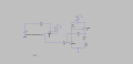
I am in the process of designing a comparator circuit I want the output of this comparator to then go into a simple BJT latch which keeps an LED on (i.e. if an error occurs, the LED remains on). I have attached screen shots of the simulations I carried out the issue I am having is that I have been able to get the latch work on it's on and the same for the comparator however when connecting the two up I am having an issue the latch functionality ceases to exist I am quite puzzled as to how I can fix it and any assistance would be greatly appreciated.
Kind Regards
Art
Attachments
-
 206.1 KB Views: 16
 -
 203.1 KB Views: 17
 -
2 KB Views: 0
-
2.7 KB Views: 3