BJT Audio Amp Design

Thread Starter

Q-Point

Joined Apr 11, 2015
9
Hello,

I am designing an audio amplifier using BJT's and I was hoping for some advice before I buy components and put it on a board. My requirements are as follows:

Voltage Gain: Av = 50;
Input Impedance > 70 KΩ
Output Impedance < 8Ω
Available power supplies are voltage regulated +12V and –12V.
fL=20Hz fH=20KHz
Maximum Symmetrical Swing = At least +/- 1.2V

My design uses +-15V rails, this is ok.

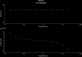
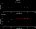
Attached are my Multisim simulation that gives me a gain of about 52. (v-probe2/v-probe1)

My input impedance matches R1 for most frequencies between 20 - 20k. I calculated this with (v-probe1/i-probe1) - Is this a valid way to calculate the input impedance?

I measured output impedance the same way (v-probe2/i-probe2) - It looks good right around 8 ohms.

The frequency response is off, (picture attached) - I get no cutoff. Id rather not build filters as I hear that is a good way to such power out of the amp, but my limited knowledge pushes me in that direction.

Other than that I used generic transistors for the circuit - I was planning on putting power BJT's on the output stage.

Any ideas help or suggestions would be greatly appreciated.

Thanks.
 

Attachments

Thread Starter

Q-Point

Joined Apr 11, 2015
9
I just realized that I simulated the frequency response from 20-20k - and I want to see what happens at the endpoints so that was kinda dumb.

Attached is a picture of my freq response now - Im not a fan of the corners, time to adjust some cap values I suppose.
 

Attachments

#12

Joined Nov 30, 2010
18,224
Just a couple of notes...R1 is way too low and you can't do current mirrors like that in discrete components. They don't match that well. The typical cure is to add some resistance in the emitter circuits.
 

Thread Starter

Q-Point

Joined Apr 11, 2015
9
Thanks for the reply,

My most recent design has R1 at 70k. I also changed C2 to get my lower cutoff more where I want it. Can you elaborate on what emitter circuit needs additional resistance and why? Im using the current mirror (Q8 and Q9) - to balance the current in Q1 and Q2 - and double my gain, are you saying that in practice this wont happen?
 

Attachments

WBahn

Joined Mar 31, 2012
30,055
Thanks for the reply,

My most recent design has R1 at 70k. I also changed C2 to get my lower cutoff more where I want it. Can you elaborate on what emitter circuit needs additional resistance and why? Im using the current mirror (Q8 and Q9) - to balance the current in Q1 and Q2 - and double my gain, are you saying that in practice this wont happen?
Do you understand how a current mirror functions?

Why is the current in the output side ideally the same as on the input side? What property of the transistors is relied upon for this to be the case?
 

Thread Starter

Q-Point

Joined Apr 11, 2015
9
Thanks for the reply.

Do you understand how a current mirror functions?

Why is the current in the output side ideally the same as on the input side? What property of the transistors is relied upon for this to be the case?
Well if emitter current is held constant, collector current will remain at a stable, regulated value so long as the transistor has enough collector-to-emitter voltage drop to maintain it in its active mode.

Therefore, if we have a way of holding emitter current constant through a transistor, the transistor will work to regulate collector current at a constant value.

Not sure if you're being condescending but thanks for the reply.

I've found some information on emitter resistors for current mirrors so I think I understand what #12 is talking about, but I honestly used the current mirror as a block, and didn't give much thought as to its intricacies.

Any more insight would be appreciated.
 

WBahn

Joined Mar 31, 2012
30,055
Well if emitter current is held constant, collector current will remain at a stable, regulated value so long as the transistor has enough collector-to-emitter voltage drop to maintain it in its active mode.
Why? What is the mechanism by which a current mirror works? Understanding this is key to understanding why a simple mirror using discrete transistors never functions very well.

Not sure if you're being condescending but thanks for the reply.
Not being condescending at all, but we need to determine where the edges of your understanding of these concepts lies.

So consider the following: I take a diode-connected BJT NPN transistor that has the emitter tied to ground and use a resistor between its collector and a 12V supply in order to establish a 10mA current through the diode. Why is it that when I connect the base of a second transistor to the base of the first (with it's emitter also going to ground) that I expect it to produce very close to 10mA of collector current even if the resistor between it and the 12V supply is considerably smaller? Why not 5mA or 20mA? What is the mechanism by which the first transistor holds the second transistor to a current of, ideally, 10mA?
 

#12

Joined Nov 30, 2010
18,224
Not sure if you're being condescending but thanks for the reply.
He's only obeying the rules of the Homework Forum. In simple form, "Don't do their homework for them. Find where they are missing a point and guide them."

We have found that you aren't sure which principle of operation can throw a current mirror off by not being stable in the real world.
 

Thread Starter

Q-Point

Joined Apr 11, 2015
9
Why? What is the mechanism by which a current mirror works? Understanding this is key to understanding why a simple mirror using never functions well.
So consider the following: I take a diode-connected BJT NPN transistor that has the emitter tied to ground and use a resistor between its collector and a 12V supply in order to establish a 10mA current through the diode. Why is it that when I connect the base of a second transistor to the base of the first (with it's emitter also going to ground) that I expect it to produce very close to 10mA of collector current even if the resistor between it and the 12V supply is considerably smaller? Why not 5mA or 20mA? What is the mechanism by which the first transistor holds the second transistor to a current of, ideally, 10mA?
The first transistor acts like a diode, and across the base emitter junction of the second, base voltage and current are held constant. The mechanism is a PN junction i guess. The only thing I can think of that would throw the mirror off is varying beta values, that would change more as one transistor heats up. I had thought of that and was going to glue the transistors together.

Is that more what you were asking?
 

Thread Starter

Q-Point

Joined Apr 11, 2015
9
Just a couple of notes...R1 is way too low and you can't do current mirrors like that in discrete components. They don't match that well. The typical cure is to add some resistance in the emitter circuits.
Because adding emitter resistors can match the BE voltage drop, right? So I need to bias the first transistor for the load of the rest of the circuit?
 

#12

Joined Nov 30, 2010
18,224
Now you have it. Vbe changes with temperature, but it is not a perfect match from transistor to transistor, either. You have to consider this when designing for a production run. Is the first transistor going to match the 50th transistor? How well?

So...when Ic depends on delta Vbe you can add resistance to the emitter because the resistor is a lot more stable across temperature changes than the transistor is. Besides that, if you choose the resistor to use up more voltage than the Vbe, the delta Vbe becomes less of a percentage of the total voltage in the emitter circuit.
 

Thread Starter

Q-Point

Joined Apr 11, 2015
9
Now you have it. Vbe changes with temperature, but it is not a perfect match from transistor to transistor, either. You have to consider this when designing for a production run. Is the first transistor going to match the 50th transistor? How well?

So...when Ic depends on delta Vbe you can add resistance to the emitter because the resistor is a lot more stable across temperature changes than the transistor is. Besides that, if you choose the resistor to use up more voltage than the Vbe, the delta Vbe becomes less of a percentage of the total voltage in the emitter circuit.
Great, I'm confident I can get this part improved. My goal is to use bias resistors to match Vbe across the mirror (and therefore Ic) - once I get it on a breadboard I'll let you know how it works.

How do you feel about my other two stages?

Thanks for all your help.
 

WBahn

Joined Mar 31, 2012
30,055
The first transistor acts like a diode, and across the base emitter junction of the second, base voltage and current are held constant. The mechanism is a PN junction i guess. The only thing I can think of that would throw the mirror off is varying beta values, that would change more as one transistor heats up. I had thought of that and was going to glue the transistors together.

Is that more what you were asking?
The key to the mirror is the assumption that the Ic vs Vbe curves of the two transistors are the same.

In the diode connected BJT, the Vbe will be "about" one diode drop and thus the resistor controls the amount of collector current. But this is because the diode-connected configuration results in the actual value of Vbe being "exactly" the voltage that is needed to support that particular collector current in that particular transistor. When we then connect the bases of the two transistors together, the first transistor applies that same Vbe to the second transistor and, assuming that the Ic vs. Vbe curve for the second transistor is the same as the first transistor (i.e., that the two transistors are perfectly matched), then the second transistor will have the same collector current as the first (and this is ignoring the effect of transistor output resistance due to the Early effect and other non-idealities).

So a basic current mirror will only work as expected if the two transistors are very closely matched, particularly in terms of their Ic vs. Vbe characteristics. This is something that is pretty easy to achieve on an IC (but even then it requires attention to detail in order to get really good matching) but all-but-impossible to achieve with discrete components. It's worth putting together the circuits and getting a feel for how poorly they work in reality.

By putting in emitter resistors (often referred to as "ballast" resistors), you change the circuit so that the collector current is now a function not only of Vbe, but of the of the total voltage between the transistor base and the bottom of the emitter resistor. For now let's consider this as ground and so the current is a function of the base voltage (not the base-emitter voltage). As you make the ballast resistor larger, you have to increase the base voltage to get the same collector current in the diode connected BJT. When this voltage is applied to the other transistor you don't need to get the same Vbe drop to get almost the same drop across the ballast resistor and it is this voltage that now determines the collector current. By choosing ballast resistors that have voltage drops of at least one diode drop you almost completely remove the transistor characteristics from the equation and can make a mirror using a small signal transistor and a power transistor and get very good performance. You can also very easily scale the input and output currents by adjusting the ratio of the ballast resistors.
 

Thread Starter

Q-Point

Joined Apr 11, 2015
9
Thanks very much for the effort in your reply, I do appreciate it.

WBahn how do you feel about the rest of the circuit, anything else catch you eye as deficient?

I'm still working on getting my frequency response to be where I want it, I run into cap values that don't reasonably exist, any ideas there?
 

#12

Joined Nov 30, 2010
18,224
Q6 is running hot. Check your numbers. I think it is survivable if I remember correctly that it is rated for 800 ma, max. This idea includes Q7.

R2 and Q1 create a parallel impedance path with R1. You could easily double the ohms in R1.

Capacitor? Be specific. Where did you try to place a capacitor and found it wouldn't work? C3 is in a place to limit the highest frequency and it looks reasonable to someone that didn't do the math (me).
 
Top