Facebook
 Google
 GitHub
 Linkedin
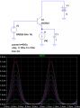
I have to design a BJT amplifier for a class lab, using a voltage divider circuit. In the diagram below we can only choose the values of the Capacitors Ci, Co and Ce and the resistors R1, R2, Rc and Re. Also, the signal generator will not allow you to get anything lower than a 120 mV p-p input signal, which sucks.

(Edit: I just noticed that I left out the ground reference and that the capacitor at the input is backwards in this image.)
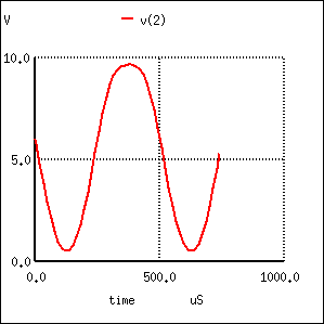
I've been biasing the transistor (which incidentally has an hFE of 160) at different Q points, all of them very close to 6V, or half the power supply voltage (which we also can't change). The problem is that I get a distorted output signal where the positive cycle is wider than the negative one. Pretty much like in this image:
Now, this seems to be a common issue with this configuration, as there is no negative feedback in the emitter, and I did find a good thread where a similar question is asked (http://forum.allaboutcircuits.com/showthread.php?t=38466). I am convinced that this is a result of the nonlinear relationship between changes in Vbe and the corresponding change in Ic. (There seemed to be a little debate on this in that thread but the nonlinearity explanation seems to be the consensus in different sources as well as in http://highered.mcgraw-hill.com/sites/dl/free/007252362x/302747/Chapter_6.pdf pages 373-376).
The question is, are there any methods for determining an optimal Q point where the distortion is minimal? Or just any other ideas that may help towards decreasing the distortion, keeping in mind that the configuration cannot be changed. I have tried with different Icq's like 1mA, 6mA and 10mA but to no avail.
Thanks.
(Edit: I just noticed that I left out the ground reference and that the capacitor at the input is backwards in this image.)
I've been biasing the transistor (which incidentally has an hFE of 160) at different Q points, all of them very close to 6V, or half the power supply voltage (which we also can't change). The problem is that I get a distorted output signal where the positive cycle is wider than the negative one. Pretty much like in this image:
Now, this seems to be a common issue with this configuration, as there is no negative feedback in the emitter, and I did find a good thread where a similar question is asked (http://forum.allaboutcircuits.com/showthread.php?t=38466). I am convinced that this is a result of the nonlinear relationship between changes in Vbe and the corresponding change in Ic. (There seemed to be a little debate on this in that thread but the nonlinearity explanation seems to be the consensus in different sources as well as in http://highered.mcgraw-hill.com/sites/dl/free/007252362x/302747/Chapter_6.pdf pages 373-376).
The question is, are there any methods for determining an optimal Q point where the distortion is minimal? Or just any other ideas that may help towards decreasing the distortion, keeping in mind that the configuration cannot be changed. I have tried with different Icq's like 1mA, 6mA and 10mA but to no avail.
Thanks.
Last edited:



 Seriously, the reactance of this cap has to be negligible at all frequencies of interest, so I just made it big.