Bistable multivibrator analysis

Thread Starter

luckyvictor

Joined May 31, 2010
4
Hi

I have questions about multivibrator, in particular, the bistable multivibrator.

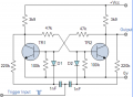
In the circuits below that I found on the internet


Why having R3 and C1 (R5 and C2) please? What do they do in the circuit?


In this design, why having D1, R6, R5 and C1 (D2, R7, R8, C2) please?

I am struggling to understand the flow of currents

Many thanks
 

Thread Starter

luckyvictor

Joined May 31, 2010
4
In the below design, looks like the triggering pulse goes to the capacitor and to the resistor, than arrive at the emitter of one of the transitor, so to use this as a trigger signal, that means this signal goes further to the base to the opposite side by one of the cross resistor.

Why do we need such a long path for the input signal to trigger the circuit please?

Can you help to explain how to current flow when, for example, the transitor at the left is turned off please?
 
Part of the reason why the circuit works is that the beta's of the transistors and the actual resistors have tolerences so simulations won't necessarily work unless you include these variables.
 

dl324

Joined Mar 30, 2015
16,839
In the below design, looks like the triggering pulse goes to the capacitor and to the resistor, than arrive at the emitter of one of the transitor, so to use this as a trigger signal, that means this signal goes further to the base to the opposite side by one of the cross resistor.
If you're referring to the bottom schematic you posted (and please post the pictures on this website; I don't have an account on the website the pictures lead to), the transistor emitters are both grounded, so no signal eventually gets to the emitter.
Why do we need such a long path for the input signal to trigger the circuit please?
It's a flip flop. The signal needs to travel from one transistor to the other to turn one or the other on and the other off.
Can you help to explain how to current flow when, for example, the transitor at the left is turned off please?
Using the picture below and using the component designators from the one your posted:
upload_2016-6-15_14-36-51.png

Assume TR1 is off. That will apply Vcc to the base of TR2 through R1 and R2. That will saturate TR2 which will keep TR1 off. So the flip flop is latched with TR1 off and TR2 on.

When a negative going trigger is applied to the junction of C1 and C2, a negative voltage will be applied briefly to the base of TR2. TR2 will turn off and TR1 is unaffected because it is already off. TR2 turning off will apply Vcc to the base of TR1 through R4 and R3 which will turn TR1 on. This will apply oV to the base of TR2 which will cause it to remain off. Now the state has toggled and TR1 is on and TR2 is off.
 

Attachments

Last edited:

Thread Starter

luckyvictor

Joined May 31, 2010
4
If you're referring to the bottom schematic you posted (and please post the pictures on this website; I don't have an account on the website the pictures lead to), the transistor emitters are both grounded, so no signal eventually gets to the emitter.
It's a flip flop. The signal needs to travel from one transistor to the other to turn one or the other on and the other off.
Using the picture below and using the component designators from the one your posted:
View attachment 107755

Assume TR1 is off. That will apply Vcc to the base of TR2 through R1 and R2. That will saturate TR2 which will keep TR1 off. So the flip flop is latched with TR1 off and TR2 on.

When a negative going trigger is applied to the junction of C1 and C2, a negative voltage will be applied briefly to the base of TR2. TR2 will turn off and TR1 is unaffected because it is already off. TR2 turning off will apply Vcc to the base of TR1 through R4 and R3 which will turn TR1 on. This will apply oV to the base of TR2 which will cause it to remain off. Now the state has toggled and TR1 is on and TR2 is off.
Many thanks.

so why the need of the diode? and when I say the long path, can't we simply connect the trigger signal to both of the base by using a resistor for example?
 

dl324

Joined Mar 30, 2015
16,839
so why the need of the diode? and when I say the long path, can't we simply connect the trigger signal to both of the base by using a resistor for example?
The circuit won't work without the diodes.

Build the circuit and experiment yourself.

You might find it easier if you first study and understand the operation of a simpler RS flip flop.
 

dl324

Joined Mar 30, 2015
16,839
None of the component values are particularly critical. The important thing is to make sure the transistors are getting sufficient base current.

R6 and R7 can probably be omitted.
 
Top