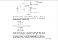
We use hfe+1 because the emitter current is equal to Ie = Ib + Ic = Ib + Ib*hfe = (hfe + 1)*Ib
And this is why Re resistor is seen at the base as (Hfe +1)*Re
We use hfe+1 because the emitter current is equal to Ie = Ib + Ic = Ib + Ib*hfe = (hfe + 1)*Ib
And this is why Re resistor is seen at the base as (Hfe +1)*Re
Sometimes you are asking about Ve/Vs and Vc/Vs, but other times it seems to morph into Ve/Vb and Vc/Vb.
What do you understand to be meant by Ve/Vb as opposed to Ve/Vs? Wouldn't Vb mean the signal voltage at the base directly, whereas Vs is the signal at the left end of Rb? So, Ve/Vb is a different gain ratio than Ve/Vs?
Please be absolutely clear which you are asking about.
If there were a capacitor across Re that grounded/shorted Re, would Ve/Vs still = \(\text{\frac{V_e}{V_s}=\frac{R_E(1+h_{fe})}{R_B + h_{ie} + R_E(1+h_{fe})}}\) ?
OK, now every thinks looks good except one small detail.
The voltage gain Vc/Vs is negative because transistor in common emitter configuration have 180 degree phase shift.
When the base current increases the collector current also increases.
As you can see when input voltage is increasing ( base current also) the Vce voltage decrease. So we have 180 degrees out of phase (negative gain).
OK, now every thinks looks good except one small detail.
The voltage gain Vc/Vs is negative because transistor in common emitter configuration have 180 degree phase shift.
When the base current increases the collector current also increases.
As you can see when input voltage is increasing ( base current also) the Vce voltage decrease. So we have 180 degrees out of phase (negative gain).
If there were a capacitor across Re that grounded/shorted Re, would Ve/Vs still = \(\text{\frac{V_e}{V_s}=\frac{R_E(1+h_{fe})}{R_B + h_{ie} + R_E(1+h_{fe})}}\) ?

 Facebook
 Google
 GitHub
 Linkedin