Facebook
 Google
 GitHub
 Linkedin
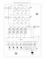
Now and then I design a project just for the halibut, and put it out there for discussion. It occurs to me thumb wheel switches are not always the best way to program times or a measurement, Binary counting uses much cheaper switches and to ant one with a little training a better way to DIY. Take resistances for example The schematic shown below show one decade range (Drawing in progress). The only design question is what wattage to mage each resistor as this could also make a decent programmable load for power supplies.

The switches are actually reversed, if they are open then the resistance is on.
This is the first decade, and also the one where we should use high wattage resistors. As they get larger in the later decades the resistors can be tweaked by paralleling them and putting small values in series.A common cheap DVM is more than accurate enough to adjust the resistances to more precise values.
Last edited: