Bidirectional MOSFET switch

Thread Starter

Aamir7264

Joined Apr 10, 2024
10
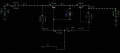
We have to use a bidirectional switch using MOSFET.
Below are the one circuit attached which i found from the itself. But that's not working during the simulation on the LT-SPICE or another software.
can anyone help me to find out the desecrate type bidirectional switch.
 

Attachments

crutschow

Joined Mar 14, 2008
38,321
You have 725kΩ in series with the 100V source, so the MOSFETs cannot be properly biased through the 100kΩ resistors to ground.

What is the reason for that high value resistor?
Obviously you will only get a small voltage at the 1.14kΩ load resistor, even if the MOSFET switch would work perfectly.

Why does the switch need to be bidirectional, when you show it with a DC voltage?

Who is "we"?
Is this a homework problem?
 
Last edited:

Thread Starter

Aamir7264

Joined Apr 10, 2024
10
You have 725kΩ in series with the 100V source, so the MOSFETs cannot be properly biased through the 100kΩ resistors to ground.

What is the reason for that high value resistor?
Obviously you will only get a small voltage at the 1.14kΩ load resistor, even if the MOSFET switch would work perfectly.

Why does the switch need to be bidirectional, when you show it with a DC voltage?

Who is "we"?
Is this a homework problem?
No its not homework problem.
Actually we have to implement the bidirectional switch in the low side(negative upto -1000V).
because of that we are going to implement this circuit.
we can use the Bidirectional switch IC but as of now we don't have budget for the IC so we are planning to use to the Discrete switch which can work in both the direction.
If you have any idea or circuit to do this activity please help me out in this.
 

AnalogKid

Joined Aug 1, 2013
12,044
Besides the things already pointed out . . .

1. Reverse the two FETs so their sources are connected together, and the drains go to the source and the load. Now you need only one resistor to pull up both gates in the off condition.

2. Delete the two diodes.

3. For a positive voltage source, change the FETs to p-channel types.

4. If the goal is to have the 100 V source appear across the load, then you will have to add a zener diode to the gate circuit, and relocate the 100K pull-up resistor.

What is the peak load current required?

AND - Reference Designators - !

ak
 
Top