Bi Pen LED W/ Flash module

Thread Starter

25Raydo00

Joined Jul 30, 2019
12
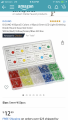
Hey, I’m trying to figure out how to get some “5mm Bi pen LED’s work off of an LED LIght controller. The ones I have I couldn’t get working but I think it may be they are just old and worn out.

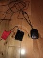
Basically it’s for a project RC truck and I’m trying to get them to flash. A buddy told me the lights will work right off of the light controller but I cant get them to. Can anyone explain to me how I can get them to work? The first picture of lights is what I’m going to buy. And the other two are the controller
 

Attachments

iimagine

Joined Dec 20, 2010
511
That controller is most likely for 12V leds string or leds array light, you cant just connect it to a bunch of random leds expecting it to work, you'd probably burned out a bunch.
 

SamR

Joined Mar 19, 2019
5,040
To start with the LEDs are not the flashing type and will need an ON-OFF signal to flash them. Then lets see a circuit diagram for the controller?

Third, Welcome to AAC!
 

Thread Starter

25Raydo00

Joined Jul 30, 2019
12
I think he means his RC controller...
My plan was to just hook them up to the led light module in the picture, mount that somewhere inside the body of the truck, and just throw a toggle switch on the power supply.

Because funnily I had some 194 led lights that I threw on the controller out of my truck doors just to see if they worked and they did. I just wasn’t sure if these small of lights would work off of it
 

iimagine

Joined Dec 20, 2010
511
You wire them like this:
DeleteMe.PNG
But then you'll have to calculate the resistor value for each color LEDs because they have different Forward Voltage.
You can google LED resistance calculator, there are many out there.
Note that wiring them like this is usually not recommended, but works
 

SamR

Joined Mar 19, 2019
5,040
It's 20mA EACH and when wired in series if one burns out they are ALL off. So they should be wired parallel each with a dropping resistor to protect it. What is the wiring diagram of your controller you are going to drive them with?
 

Thread Starter

25Raydo00

Joined Jul 30, 2019
12
It's 20mA EACH and when wired in series if one burns out they are ALL off. So they should be wired parallel each with a dropping resistor to protect it. What is the wiring diagram of your controller you are going to drive them with?

At work right now, and I’m not sure on the diagram of the controller. I can see what I can find on it when I get home tonight
 
Top