Bi-directional audio Op-Amp

Thread Starter

Diego Tavares

Joined Jul 28, 2018
4
Hello guys!
I'm using an Arduino Uno to make a RGB light pattern based on sounds from a microphone (actually it's an old little speaker) and for making some 8 bits music, just for fun :). Connecting the speaker directly to the arduino I/O and to GND it could get some weak signal from loud sounds and make some almost inaudible music, but worked almost better than i expected XD
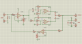
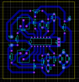
I have been using in this config by days, but today i finished my PCB for my prototype of bi-directional audio amplifier based on a TL074 and plugged it on the Arduino, and now the problems begin.
1°- The receiving signal is impossible to read (As i don't have acess to oscilloscope, just the arduino).
2°- The output signal is lot weaker than directly to Arduino
3°- I used some examples from some forums and online calculator tools to make the parts of this circuit. The variable gain and the crossover i searched for audio specific applications, but the thing of putting the 2-way amplifier was from random applications with others AmpOps, so i'm thinking that this would be ruining the circuit.
 

Attachments

AnalogKid

Joined Aug 1, 2013
10,986
What do you mean by "bi-directional audio"? What is it you are trying to achieve?

The circuit has a large amount of positive feedback. This will not work as a speaker amplifier. Is the speaker supposed to be the input, the output, or what?

As above, there is nothing to bias *any* of the opamps into a linear active region. U1A and D are acting as half-wave rectifiers, and U1 B and C are confused.

And finally, the TL074 cannot operate on a single 5 V rail. Per the datasheet, the minimum is +5 V and -5 V. Also per the datasheet, the input common mode range (the range of input voltages where the part functions as a linear amplifier) is going to be very small at these low operating voltages.

ak
 

sghioto

Joined Dec 31, 2017
5,376
And finally, the TL074 cannot operate on a single 5 V rail.
Actually it does work on a single ended 5 volt supply. I verified using a TL071 with the + input biased at half the supply voltage. Max output is 2 volts p/p.
The circuit the TS posted is not biased properly using a single supply. However will work with a dual supply.
SG
 

AnalogKid

Joined Aug 1, 2013
10,986
Basing the success of a design on an uncontrolled and undocumented feature is not something to be encouraged, especially in someone without the experience to know the pitfalls. See Line 2 and Note 1.

ak
TL074-cut.gif
 

sghioto

Joined Dec 31, 2017
5,376
Getting back to circuit in post #1 I don't understand this Bi-directional approach.
Digressing here it seems you want to amplify some sound using a speaker as a mic.
Pass this audio through two filters and select one or the other to be processed by the Arduino.
If this is correct then the revised schematic below might work.
Note this uses a bi-polar 5 volt supply
SG
EEE TL074 amp to Arduino.PNG
 

Thread Starter

Diego Tavares

Joined Jul 28, 2018
4
I assume speaker is ground referenced. Your signal chain is single supply,
but speaker output swinging below ground ? If true the input amp needs to
biased properly.
Yes, you are correct. I agree that i will lose a lot of signal by not processing the negative signal, but i don't really need this signal bellow ground, as my objective is just read the signal to generate some cool effects in a RGB led and output some 8 bits music with square waves. You lead me to a doubt, would this interfer in the functionality of the circuit or the amplifier will fail to process just half wave? If this is a problem, i could bias the signal or just give a negative supply to the TL074?


What do you mean by "bi-directional audio"? What is it you are trying to achieve?

The circuit has a large amount of positive feedback. This will not work as a speaker amplifier. Is the speaker supposed to be the input, the output, or what?

As above, there is nothing to bias *any* of the opamps into a linear active region. U1A and D are acting as half-wave rectifiers, and U1 B and C are confused.

And finally, the TL074 cannot operate on a single 5 V rail. Per the datasheet, the minimum is +5 V and -5 V. Also per the datasheet, the input common mode range (the range of input voltages where the part functions as a linear amplifier) is going to be very small at these low operating voltages.

ak
Sorry not to say the objetive, i think it get confuse. My objetive is to use the speaker as a input and output, so in the arduino i can treat this I/O pin on the program to sometimes receive signals from the speaker on the A/D converter and sometimes send signals to play in the speaker. The input function is to detect the ambient noises and music and feedback with a blinking pattern on a led and the output signal to speaker would be to play alarms and other random sounds, the "bi-directional" amplifier is to use just 1 speaker and 1 pin on arduino (if it's possible to made this type of circuit).
I'd tested my program using the speaker connected directly to the arduino I/O pin and GND with a 220K resistor parallel with the speaker to stabilize the signal on 0V, it worked well, it could get some voltage from the speaker with loud sounds and the arduino could play musics like caribbean pirates theme song. The program and the speaker wasnt the problem, so i mess making up this circuit.
I didnt understand what do you mean with "large amount of positive feedback".
The U1 A and D i copied from some variable gain amplifier circuits examples and U1 B and C are supposed to be the crossover, so i could get just low or high frequencies from the speaker, i used a online design tool. I don't know if i'm allowed to do this, but this is the tool that i used: https://www.analog.com/designtools/en/filterwizard/
As the TL07x work with dual supply voltages, it wouldnt be nescessary to bias the signal right? Just making this with a dual supply instead of a single supply can resolve? But with a single supply voltage and no biasing point, it would work? Even than using just half-wave?
I do looked the datasheet, but i gess that i dont read it right, i didnt see that minimum voltage was +/-5V and this amplifier wasnt rail-to-rail. And now you give me a doubt, some amplifiers are unable to give the output signal close to 0V right? Would be TL07x one of them? If true i would be getting a signal a little higher than 0V and pretty lower than 5V on the output? If this is correct it explain why the sound made by the speaker was too weak and the signal read was too confused.

Actually it does work on a single ended 5 volt supply. I verified using a TL071 with the + input biased at half the supply voltage. Max output is 2 volts p/p.
The circuit the TS posted is not biased properly using a single supply. However will work with a dual supply.
SG
So, using the TL with a single power supply could be done? But the same doubt here, is there a problem to rectify the signals? Because the arduino dont process negative voltages, so i was thinking in excluding this part of signal. This circuit could work as a half wave amplifier or i'm messing up the signals?

Basing the success of a design on an uncontrolled and undocumented feature is not something to be encouraged, especially in someone without the experience to know the pitfalls. See Line 2 and Note 1.

ak
View attachment 175247
Sorry to seem too negligent. Maybe this could be the wrong way to approach a "bi-directional" circuit. I don't really give the necessary attention to datasheet of the TL07x, but i knew that it's used a lot for crossover and audio processing in power amplifiers (mostly 12v single supply with biasing point), so i almost copy identical to these crossover schematics with my necessity (with 5v single supply and no biasing) and put the stage to control the gain. But the thing of putting the aditional amplifier going the other way i didnt really searched about...as AlbertHall said, i will try to isolate the circuit, making it a just input or output circuit.
The logical of the circuit is right? Not thinking now about having the U1 D part of circuit, just the gain control and the crossover section to receive signals from the speaker. Or maybe would i change this TL074 for another operational amplifier like a OPA1679? (this work in 5V single supply and is a rail-to-rail amplifier).

Getting back to circuit in post #1 I don't understand this Bi-directional approach.
Digressing here it seems you want to amplify some sound using a speaker as a mic.
Pass this audio through two filters and select one or the other to be processed by the Arduino.
If this is correct then the revised schematic below might work.
Note this uses a bi-polar 5 volt supply
SG
View attachment 175256
Well, i do made this a little confuse, but explained better in the upper lines.
My approach was to use the speaker as a mic, so i put the U1 A as a input signal gain control and U1 B and C are for low and high pass filters, selected by the 2-way jumper and taking this processed signal to the arduino.
But my idea was to make this circuit able to deliver amplified audio signals to the speaker too, so i put that U1 D on oppose direction of others amplifiers.
As you revised the schematic, you put the U1 D to complement the output of the filters and put a -5V supply right? That was not what i was trying to archive, but you got me a good question: You made the U1 A an initial gain control and the U1 D the post gain control. There is any difference in controlling the gain after or before the crossovers?
You don't made any radical change in the circuit, so i presume that i do almost everything right...So letting aside the part of trying to made this a two-way amplifier. So as you said, the TL can be used with a single volt supply, and as AnalogKid alerted, Vcc+ - Vcc- should be between 10V and 30V, if i change the voltage to +12v and isolating U1 D from the circuit it would work? Even that losing the negative part signal logical, but as i mentioned, i just need half-wave of the signal (and if in the future i need the full wave i would just add a negative power supply or bias the input).

Disconnect R7 and see whether it works.
I will isolate and test the parts of the circuit and give you some feedback.
 
Last edited:

AnalogKid

Joined Aug 1, 2013
10,986
I understand what you are trying to do, but you cannot have amplifiers in both directions enabled at the same time. The two amps form a loop that will either oscillate or latch up. Plus, an opamp output has a low source impedance. If the speaker is connected to it, that low impedance will swamp, or almost short out the very small signal coming from the speaker when it is acting as a microphone. The best way is to use three Arduino pins: one for input, one for output, and one to switch the external circuit between the two functions.

ak
 

Audioguru

Joined Dec 20, 2007
11,248
If you buy a few hundred TL07x opamps, you might find a few that barely work when the single supply is too low at only 5V Use 9V or more.
TheTL07x opamps have a problem when an input voltage is within a few volts from its negative supply (0V in your single supply circuit) causing its output to go as high as it can and not amplify. The input DC bias must be at about half the supply voltage, not near 0VDC.

Use a single 9V or more supply and use two resistors in series to bias the (+) input of the first opamp at half the supply voltage and use an input coupling capacitor from the speaker. Then the input and the output of the opamp can swing up and down with sounds. Also connect a capacitor from the bottom of the gain control pot to 0V.

The output current from an opamp is too low to drive a speaker, use a power amplifier like an LM386 instead.
Here is how the first opamp should be connected:
 

Attachments

Thread Starter

Diego Tavares

Joined Jul 28, 2018
4
I understand what you are trying to do, but you cannot have amplifiers in both directions enabled at the same time. The two amps form a loop that will either oscillate or latch up. Plus, an opamp output has a low source impedance. If the speaker is connected to it, that low impedance will swamp, or almost short out the very small signal coming from the speaker when it is acting as a microphone. The best way is to use three Arduino pins: one for input, one for output, and one to switch the external circuit between the two functions.

ak
Oh, now i get it well, i'm going to think more before inventing some crazy circuit design :D guess i will isolate input and output and use a proper mic and make it in more conventional way.

If you buy a few hundred TL07x opamps, you might find a few that barely work when the single supply is too low at only 5V Use 9V or more.
TheTL07x opamps have a problem when an input voltage is within a few volts from its negative supply (0V in your single supply circuit) causing its output to go as high as it can and not amplify. The input DC bias must be at about half the supply voltage, not near 0VDC.

Use a single 9V or more supply and use two resistors in series to bias the (+) input of the first opamp at half the supply voltage and use an input coupling capacitor from the speaker. Then the input and the output of the opamp can swing up and down with sounds. Also connect a capacitor from the bottom of the gain control pot to 0V.

The output current from an opamp is too low to drive a speaker, use a power amplifier like an LM386 instead.
Here is how the first opamp should be connected:
It was my bad not to pay enough attention to the datasheet and design notes for the LM074. But i'm going to remake this circuit in a more proper way. I really couldnt find the output current of TL07x, but the speaker have less than 1W.

Thank u all :) i guess it's a resolved topic
 

Audioguru

Joined Dec 20, 2007
11,248
With a supply of +/- 15V, a datasheet graph shows 11V into a 1k load which is 11mA. With a +/- 4.5V supply the current is probably less.
With the +/- 15V supply and the 11V peak into a 1k load, the RMS voltage is 11V/1.414= 7.8V RMS then the power in the 1k load is only 0.06W.
into an 8 ohm speaker the loudness will sound like a little earphone. But with your +/- 4.5V supply you will barely hear anything.

An LM386 little power amplifier has a maximum output current of 375mA into an 8 ohm speaker when its supply is 9V which is 0.56W, about as loud as a cheap clock radio.
 
Top