Best way to get maximum capacitor discharge current?

Thread Starter

Ritalie

Joined Sep 5, 2016
4
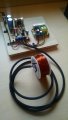
Hello, I have designed a simple 400 volt magnetic coil (solenoid/electromagnet) driver circuit, using an SCR, a capacitor/s, and a copper electromagnet.

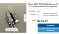
There doesn't seem to be any type of capacitor specifically designed for high intensity coil driving circuits, other than 330 volt "photo flash" type.

Is there any disadvantage to creating a 660 volt capacitor bank of 10 cheap photo flash capacitors, by using twice as many capacitors, with 2 separate rows of 5 capacitors connected in "parallel" then connecting each bank together with a "series" connection?
 

Attachments

LowQCab

Joined Nov 6, 2012
4,026
It's best to purchase Capacitors with the exact specifications
that your Circuit requires.

The Duty-Cycle of your Solenoid,
and the associated Heating of all of the Components,
including the Capacitors,
will determine the life expectancy of all the Components.
.
.
.
 

Papabravo

Joined Feb 24, 2006
21,159
The title of your thread indicates a fundamental misunderstanding of capacitors and circuits that use them.
  1. The maximum current of a discharge happens at the instant the discharge circuit is completed.
  2. The maximum magnitude of the current depends on the resistance of the discharge circuit.
  3. The current in the discharge phase of operation decreases exponentially with a time constant, in seconds, of R*C, where R is the discharge resistance in ohms (Ω), and C is the capacitance in farads.
The other part of your question in regards to series and parallel combinations of capacitors requires that you understand how to calculate the total capacitance of a given combination of capacitors in series and parallel connections. A secondary problem is to determine the safe working voltage of the combination. Failure to understand what is going on can be dangerous at the power levels that you are using. Stressed capacitors can explode violently with shrapnel, super heated steam, and toxic aerosols.
 
Last edited:

shortbus

Joined Sep 30, 2009
10,045
Those photo flash capacitors have a limited life, from what I understand. There are some caps called Pulse Capacitors, that seem to be made for just that. In one of my ongoing projects, a pulse discharge EDM amchine , I did a lot of research into caps for it. My first idea was the photo caps, but then I found out there were caps made to do what I want. https://www.wima.de/en/our-product-range/pulse-capacitors/ Those are reported to be the standard to measure against, for a pulse cap, but other companies do make them.
 

Papabravo

Joined Feb 24, 2006
21,159
I'm still unclear about the method and purpose of "driving" an inductor from a capacitor. What is the point exactly?
For an EDM machine, I would think that a constant current from the tool head to the workpiece, would be the way to go, and I don't see how a charged capacitor would be helpful in that application.

My only experience using an EDM machine was removing a hardened tool bit from a workpiece that I did not have time to remake. It was for a class, and I'm glad I had a sympathetic instructor who helped me salvage the almost completed project.
 

shortbus

Joined Sep 30, 2009
10,045
For an EDM machine, I would think that a constant current from the tool head to the workpiece, would be the way to go, and I don't see how a charged capacitor would be helpful in that application.
I am not driving an inductor, if this is meant for me. The reason for pulsed caps in an EDM is to get a better surface finish and faster burn. The caps discharging into the burn keep each spark the same size and frequency, unlike the older ones that used a RC circuit to oscillate the discharge.

But it wasn't my intention to hijack this thread, just an explanation of how I found there are pulse caps.
 

Papabravo

Joined Feb 24, 2006
21,159
I am not driving an inductor, if this is meant for me. The reason for pulsed caps in an EDM is to get a better surface finish and faster burn. The caps discharging into the burn keep each spark the same size and frequency, unlike the older ones that used a RC circuit to oscillate the discharge.

But it wasn't my intention to hijack this thread, just an explanation of how I found there are pulse caps.
This thread has conflated several topics that may or may not have any relationship with each other. I am henceforth adopting the policy of @crutschow No schematic, no comment.
 
Top