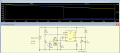
I ran a sim of the right-hand half of the circuit in LTspice and agree with your results: Q3 collector never gets high enough for T3 to get triggered.
I would probably have used a circuit such as below to terminate the discharge at a set battery voltage :-
Here, TL431 provides a reference voltage settable with a trimpot.
At power-up, R1C1 keep the Trig input of the 555 low for a brief period to trigger the 555, pin 3 of the 555 then goes high and the relay coil is energised. As the supply voltage drops, the input to the internal comparator inside the 555, which is about 2/3 the supply voltage, drops below the reference voltage so pin 3 goes low and de-energises the coil. Even if the supply voltage bounces back up, the 555 is not re-triggered.
Thanks for that. Now all I need to do is work out what to do with it
Do you have an "uncompiled" -- is that the right term? -- version? I'd like to see what is inside.
Also, I think I've worked out (another part of) why I been having such inordinate trouble understanding this circuit.
The sim I'm using requires 3 parameters to define an SCR. Trigger current, holding current and Gate-Cathode resistance.
Looking at the datasheets from two different manufacturers of the MCR100-6; Microelectronics & Taiwan Semiconductor; the first two are 200uA and 5mA respectively; but the Gate-Cathode resistance is less clear (to me).
The only mention of resistance that seems applicable on either datasheet are both in footnotes and are identified as RG-K 1kΩ and R[sub]G-K[/sub] 1kΩ; so that's what I've been using. But it seems (to me; with my lack of knowledge) very high.
For example: In the OP schematic, for the wall wart to charge the battery at a realistic rate (the WW is rated at 200mA), T1 would need to pass a current of ~200mA; but at 15V (it'll be less because of D5) and 1k, the most it could pass is 15V/1kΩ = 15mA.
Ditto for T2 & T3. To pass sufficient current to fulfill their role in the circuit, a 1K 'internal' resistance is too much at 15V.
QUESTION: Have I misinterpreted the datasheets? Is RG-K the "Gate Cathode resistance"?
If I drop the Gate cathode resistance parameter on all 3 SCRs to 50Ω (determined by experiment); the entire circuit seems to function much closer to reality. The red/green LEDs light at appropriate voltages(T2); Q4 cuts off once the voltage drops (T3); and T1 allows more than uAs to flow to charge the battery, when the supply voltage is sufficiently higher than the battery.
It's not perfect. The simulator still craps out with "Convergence error" if the battery voltage is too much less than the supply -- any difference greater than 2V seems to cause this -- but it comes a lot closer to what I measure in reality than with the 1k gate-cathode resistance value the specs seem to define.
I would probably have used a circuit such as below to terminate the discharge at a set battery voltage :- View attachment 147712
Here, TL431 provides a reference voltage settable with a trimpot.
At power-up, R1C1 keep the Trig input of the 555 low for a brief period to trigger the 555, pin 3 of the 555 then goes high and the relay coil is energised. As the supply voltage drops, the input to the internal comparator inside the 555, which is about 2/3 the supply voltage, drops below the reference voltage so pin 3 goes low and de-energises the coil. Even if the supply voltage bounces back up, the 555 is not re-triggered.

 Facebook
 Google
 GitHub
 Linkedin